There’s more to an exercise ball than you thought

Identify

Anyone who has ever been to the gym has most likely seen or used an exercise ball. They’re big, inflatable balls that many people use to help them facilitate exercise or to stretch. They’re good for strengthening your core and improving your balance. Incorporating an exercise ball into your daily workout will add a challenge to your routine. A lot of people may also use them at home due to the fact that they are very affordable and versatile. While they may seem harmless, there can be serious risks when using one. It is important to use the correct size ball based on your height in order to get the most effective workout. It has to be inflated properly in order to work correctly. An over or under inflated exercise ball will put you at a greater risk for injury. The biggest danger of an exercise ball is having it burst. Over-inflation, improper use, and excessive user weight are some common ways that the ball may burst. The first step in preventing an exercise ball from bursting is choosing the right material. The material needs to be able to support the user and keep the integrity of the ball. Some common materials are vinyl and plastic. It’s important to figure out the force that is being applied to the ball, in order to figure out the strength of the material needed. The material needs to have a high tensile strength to support the user and prevent the ball from bursting and injuring the user.

Example of Exercise Ball


Formulate

The first step is figuring out the appropriate size of the ball based on height. When sitting on the ball, your knees should be at a right angle and your thighs should be parallel to the ground. The average woman in the United States according to the CDC is 64 inches tall and 166 lbs (75.3 Kg). According to anthropometric dimensional data, the ground to her knees is .285 (Anthropometric data-197t3u3) of her height.

.285 * 64 inches = 18.24 inches

Proper size for an exercise ball based on height


This means that the proper exercise ball should be 18 inches in diameter or 46 centimeters.

To find the best material, we can calculate Young’s modulus based on Hooke’s Law. 


Hooke’s Law  

?= stress = Force/Area

E= Young’s modulus

ɛ= strain= Δl/l

Surface Area of Sphere = 4 * π * r^2

Assumptions:

  • Exercise ball undergoes elastic and linear response to force
  • All of the users weight is being applied over the top half of the ball
  • Assume the exercise ball displaces 1 inch when force is applied

Solve

?= Force/Area

Force = 75.3 Kg * 9.8 m/s^2 = 738 Newtons

Half the area of sphere = ½ * 4 * π * 9.12^2= 523 in^2 = .337 m^2

? = 738 N / .337 m^2 = 2190 N/m^2

ɛ= strain= Δl/l

Ɛ = 1 inch/18.24 inch = .0548


2190 N/m^2 = E * .0548

Young’s modulus: E = 4.00 x 10^4 Pa


From this calculation, an exercise ball would need to be made of a plastic or vinyl with a Young’s modulus of around 4.00 x 10^4 Pa.

The assumption that the user’s total weight is distributed on the entire top half of the exercise ball led to the Young’s modulus to be underestimated. In real life, the user’s full weight wouldn’t be on the ball and it would also be distributed over a smaller surface area. The actual material would have a higher Young’s modulus than the calculated value. 


Learn more about the things you can do with an exercise ball!

http://www.webmd.com/fitness-exercise/features/10-fun-moves-to-reshape-your-body-with-exercise-ball-workout#1

http://www.fitnessmagazine.com/workout/exercise-ball/best-stability-ball-exercises/

Exercise Balls – The Ultimate Guide


Physical Therapist’s Tool of Choice- Hand Held Dynamometers

Identify

For physical therapists, one of the most important and sometimes most challenging aspects of their job is to track patient progress during rehabilitation from an injury or surgery.  While most of this can be done based on patient reporting (such as 1-10 pain/discomfort scales) or qualitative therapist observations, they collect quantitative data whenever possible.   One of the most common ways therapists can document progress is through strength testing.  For larger muscles, such as the quad and hamstring, larger testing apparatuses, like the Biodex, are used to measure strength. These machines, however, are large and difficult to use. They can be oriented for smaller muscles but almost always therapists will opt for hand-held dynamometers. Over the years these dynamometers have developed from simple spring or strain gauge contraptions to sleek digitalized devices.

The RIHM (Rotterdam Intrinsic Handdynamo Meter)

Taheel Technology Hand- Held Electronic Dynamometer

The above dynamometers are used to test grip strength and for the sake of explanation I will focus on this orientation., It is important to note that clinics often use the device shown below to measure strength of the arm and shoulder region since it allows for measurements to be taken in many different directions. For example, knowing the internal rotation and external rotation strength of a baseball players injured arm in comparison to his healthy one will allow the therapist to decide when the player should be allowed to return to play.


As I mentioned, all of these devices are designed on the seemingly simple basis of springs and strain gauges, Therefore, when designing a dynamometers the starting point is to decide what spring to use. If the spring constant is not stable and known, the device cannot be calibrated and will not result in accurate readings.


Formulate

For a grip strength dynamometer the patient pulls on a a handle connected to a spring of a known constant. Based on the displacement of the spring from it’s resting position the force they generated can be calculated.  This force is a direct measure of grip strength.  To decide the stiffness of the spring that should be used an engineer must use Hooke’s Law:

Hooke’s law states that the force of extension on the spring is proportional to the displacement of the spring.

The following assumptions can be used to calculate the max spring constant that should be used:

  • Force (Fs)– According to a study done by Top End Sports the maximum grip strength the dynamometer must be able to withstand is 57.5 kg.
  • Displacement (x)- Based on average hand sizes it can be assumed that the maximum displacement of the spring will not exceed 9 cm.

Fundamentally, stiffer springs have higher spring constants. For this reason, we know that the spring constant should be minimized, yet must be able to detect the max force and displacement it may experience. You essentially do not want to make it harder than it has to be for the patient.

Using these two assumptions and an understanding of Hooke’s Law it can be determined what the max spring constant that will be needed.


Solve

The following steps are used along with the assumed values to determine the ultimate spring constant:

F=-kx

57.5 N=-k(0.09 m)

k=-638.889 N/m

According to these calculations, a spring with a constant below approximately 640 N/m will suffice in your design of a handheld dynamometer.

Now it is important to understand the implications of the assumptions made here so your design can be altered for maximum efficiency.  It is necessary to consider the patients that will be using your design.  While the calculations above are generalized for average sized patients this may not fit your needs. For example, if your device will be used by pediatric patients the assumed values can be much lower whereas if your device will be used by athletic trainers in professional sports, the numbers should probably be increased.

The development of such dynamometers has been on the rise as their clinical prevalence has also risen.  They are extremely beneficial to clinicians yet are based on such a simple engineering principle.

For more information on the benefits and design of dynamometry I encourage you to check out the following readings:

http://www.prohealthcareproducts.com/blog/handheld-dynamometers-and-manual-muscle-testing/

https://www.ncbi.nlm.nih.gov/pubmed/18796949

https://www.ncbi.nlm.nih.gov/pmc/articles/PMC2868792/

Wheel on Up, Pull on Down

Many common diseases such as Multiple sclerosis, Cerebral palsy, and Post-polio syndrome as well as traumatic brain and spinal cord injury, strokes, and tumors can lead to Paraplegia, or paralysis below the waist. While paraplegia of course is limiting, upper-body exercise and strength building is vital to establish an active, independent, healthy lifestyle. Exercise for those with spinal cord injuries and paralysis have also been shown to decrease the risk of developing many associated secondary conditions such as osteoporosis, cardiovascular disease, pressure ulcers, urinary tract infections, diabetes and arthritis. Exercising has also been shown to control pain, improve mental health, and maintain a healthy weight for those with limited mobility. However, the number of possible exercises are limited by a lack of accessible equipment and resources for people with limited mobility.

     Image 1. Diagram of muscle groups targeted by the lateral pull down machine.

An example of a piece of equipment that could increase upper body strength is a lateral pull down machine as shown above in Image 1. This machine is used in a sitting position and the user grasps the bar with palms facing forward and pulls the bar down toward their chest. This exercise targets the rhomboid major, latissimus dorsi muscles, located on the sides of your rib cage, the biceps, the lower trapezius, and the posterior deltoid in the back of the shoulder, all of which contribute to a stronger upper body.

Because this piece of equipment is composed of a bench and thigh stabilizer, someone in a wheelchair would not be able to use it to build their upper body strength without assistance to move out of their wheelchair. This is an issue for several pieces of upper body strengthening equipment. The question is, how could these pieces of equipment, the lateral pull up bar particularly, be altered to provide more independent access to those in wheelchairs without taking away from their current effectiveness? If this question were to be solved, perhaps it could lead those with limited mobility to feel more comfortable at community gyms and provide them with a means to exercise more independently.

Assumptions and Estimations:

  • Average arm length (young man with average height): 25 inches
  • Average armrest of wheelchairs: 30 inches
  • Height of resting bar combines the height of the armrest of the wheelchair and average arm length above, minus 5 inches to account for women as well
  • Average height of chairs: 19 inches
  • People perform pull down correctly and reach straight up to get bar
  • We are calculating force at hinge, each horizontal measurement to calculate moment is taken from this origin
  • Height of bench is 2 inches (measured at UD gym)
  • Height of stabilizer varies, but maximum would be 7 inches away (measured at UD gym)
  • Weight of bench is 5lbs
  • Weight of stabilizer is 1lb
  • Weight of each member is 6lbs

Image 2. Dimensions of standard Stack Loaded Lat Machine by Deltech Fitness, shows typical set up of the Lateral Pull Down Machine

As shown in Image 2 above, which is similar to most lateral pull down machines, the first aspect that requires adjustment is the dimensions. The width of the area where the wheelchair could pull in would have to be increased to a width greater than 32 inches in order to meet ADA standards for doorways. The bench and thigh stabilizer would also have to be adjusted so it could be cleared away from the area in which the wheelchair will sit. This machine can be altered by increasing the width to 33 inches and implementing a foldable bench/stabilizer mechanism that can be pushed up to the left or right side as shown below in Image 3a and 3b.

Image 3a (top) and 3b (bottom): 3a – Overlooking design of lateral pull down machine with updated dimensions that allow those in wheelchairs to access, as well as a removable bench that can be folded up. 3b – Image of bench and members in folded up position showing weight distribution centered around the hinge.

Using the following equation to determine moment on hinge:

|Mo| = (Force) * (Perpendicular distance)

and taking into account all assumptions and measurements used, the torque on the hinge can be calculated using the following values:

(Wbench*Distancebench) + (Wstabilizer *Distancestabilizer ) +(Wmember1 + Wmember2)*(Distancemembers)

(5lbs*20in)+(1lb*28in)+(12lb*9.5in) = 242 lb*in

The total torque on the hinge calculated is  242 pound inches. An off-set hinge made out of stainless can be used which provides a greater length on the ground to counter the force caused by the hanging bench. Reaching the bar is another issue for those in wheelchairs. To combat this issue, the wire can be lengthened so that the resting position of the bar should be 50 inches off the ground in order to provide access to those who are sitting without having to get up.

 This solution is assuming a standard size of wheelchairs which is used by the ADA when performing construction of doorways, however, wheelchair height and widths do change and not all will be able to fit in this gap. Exceptionally tall people may also suffer from these changes, as the wire length increase was done to help an average height or lower person. Those who are a lot taller may not gain full effectiveness of a pull down if they are starting lower than the top of their arm span reaches. This solution is indeed reasonable for those that have disabilities requiring the use of wheelchairs, however it is difficult to enact global changes such as this for development of equipment as the majority of users have the ability to use machines like this without these changes. Changes have to be encouraged by all to improve the accessibility to healthcare and exercise to all groups, even those who are marginalized. The value for the torque on the hinge makes sense, as it is carrying the full weight of the bench and the members that typically support the full weight of the user.

This solution may also need to be adjusted because sometimes gyms are limited in size and may not be interested in the fold up chair that could potentially take up more space than the original version. Coming back to the original question, this solution shows that equipment like the lateral pull down machine can be used for those who are disabled, and the development of this in gyms should be encouraged. Those with disabilities deserve the same opportunities to create a healthy lifestyle and feeling of community that comes with working out in a gym. The more independently they are able to do this, the more inclined they will be to continue. T changes in dimensions of the typical machine as well as the moveable bench allow that for those who typically would be unable to build their upper body strength in this way the ability to do so.

Additional Resources:

http://www.spinalcord.com/types-of-paralysis

https://www.ncbi.nlm.nih.gov/pmc/articles/PMC2694784

https://www.karmanhealthcare.com/how-wide-does-a-doorway-need-to-be-for-a-wheelchair/

http://www.livestrong.com/article/503333-what-are-the-benefits-of-a-lat-pulldown/


Designing Safer Cleats

Identify:

The earliest use of cleats has been reported since 1525 when King Henry VIII had a pair of soccer cleats. Since then, their design has changed drastically in order to accommodate changes in sports and technology. Today in sports there are many varieties of cleats that each provides their own advantages and disadvantages. However, as safety becomes a priority in modern sports regulation, certain cleat materials are beginning to become banned from use. Metal spikes present a hazard to players who may be stepped on or kicked. So there is a need for new cleats to be made from less hazardous materials that still provide the facilitation of rapid acceleration and deceleration in athletes.

Figure 1: A low-cut cleat with metal studs.

When athletes accelerate or change direction there is a great deal of force that is placed between the shoe and the ground. In order to prevent slips, studs on the bottom of shoes are necessary so that greater amounts of force can be reached. These studs can be replaceable or permanently attached to the sole of the shoe. Depending on the amount of force, the studs must be designed with a large enough surface area of attachment to withstand the shear stress. By understanding how much shear force each cleat stud will experience, it is possible to design a shoe with large enough studs that will not break off of the shoe when the user is accelerating.

Formulate:

In order to design a cleat able to withstand the forces of athletes there are several factors to consider. The material that is being used in the design of this cleat is rubber which provides stability and strength without the dangers of metal studs. The force applied to the studs will be greater if there are fewer studs and smaller if there are more studs. The weight and speed of the user must also be considered for the design. Heavier and faster users will generate more force when they accelerate or decelerate. It is also important to consider which sport the shoe is being designed for as different sports deal with different sized athletes and different speeds. For this design the cleat is being made for soccer players. The heaviest soccer player currently in the league weighs in at 227 pounds. With regard to slowing down and speeding up, Usain Bolt can accelerate from 0 mph to 12 mph in 1.85 seconds. So with this known weight and acceleration data, assumptions and simplifications can be made in the calculations.

 
Figure 2: Depicts the force of the ground acting on the shoe in order to accelerate the athlete in the +X direction.


Figure 3: Fground is translated into each stud separately.

Assumptions, Simplifications, Estimations, and known values

Weight: 250 pounds (more than max soccer player weight)

Acceleration: 10mph in one direction to 10mph in opposite direction in 2 seconds (faster than Usain Bolt.

10 studs on the cleat (number used in many designs)

Force in Y-direction negligible

Shear modulus of rubber is 300kPa

Equivalent force applied to each stud


Equations used:

Force = mass * acceleration

Acceleration = change in velocity / time

Area of circle = pi * r2


Solve:

Solving for force applied on each stud:

20mph = 8.94 m/s

250lbs = 113.4kg

a= (8.94m/s)/(2s) = 4.47m/s2

F= (113.4kg)*(4.47m/s2) = 506.9N

F/stud = 506.9N/10 = 50.69N = 11.4 pounds of force per stud

Solving for radius required per circular stud

300kPa = 43.51psi

SA = (11.4lbs)/(43.51lbs/in2) = 0.262 in2

0.262 in2 = (3.1415)*(r2)

r = .288 in


Each circular stud will need to have a radius of at least 0.288 inches in order to withstand the applied shear force and not be torn off of the rest of the shoe. If a heavier weight, a larger change in velocity, a shorter time period, or fewer studs were used in the calculations, the required radius would be larger than the calculated value. This value is reasonable as it would easily allow for 10 studs to be configured onto the bottom of a shoe without the need for a larger shoe sole.

However, these calculations are limited in that the forces in the y-direction were left out. The force of gravity would compress the studs into the shoe in addition to a shear force. This may result in an increase or decrease in required radius of the studs. Additionally, this assumes that only one foot is involved in the process. If both feet are being used then more studs are being applied and therefore the equivalent force each stud experiences will be decreased. Knowing the required radius though will allow for the design of a rubber cleat that can be used in a similar way to metal cleats without losing any functionality.


For more information, visit:

http://www.goldenshoesmovie.com/the-history-of-soccer-cleats-part-1/

http://footballstopten.com/top-10-heaviest-footballers/10/

http://datagenetics.com/blog/july32013/index.html

http://www.engineeringtoolbox.com/modulus-rigidity-d_946.html


Determine the thickness of resistance bands

Resistance bands have been used since the early 1900’s as an exercise tool, and are now also widely used as a rehabilitation tool to strengthen (injured) muscles and joints. They became popular due to their affordability and convenience. Just like weight training, they can increase muscle strength, endurance and flexibility. When designing a resistance band, it is important to determine several aspects, like what material to use, and how long, thick and wide to make the bands.

Image result for resistance band with handles

Figure 1. Commercially available resistance bands.


Image result for chest exercise resistance band

Figure 2. Chest exercise performed with resistance band.


The question we will consider here is what the appropriate dimensions are of resistance bands so that they are able to provide the appropriate resistance forces. It is important to be able to produce several bands that gradually increase the force needed to stretch them for several reasons. For example, strength varies between individuals and between different muscle groups within an individual so need different resistance levels are needed, and people (re)building strength after an injury need to be able to gradually rebuild with different resistance levels. Here, we will focus on circular resistance bands, and therefore the specific variable that will be determined is the radius of the resistance band.

A resistance band is usually made of natural rubber, as this provides enough strength while still stretching with the user’s movements.  Natural rubber behaves as a linear elastic material, with a Young’s Modulus (E) between 1 and 5 MPa. As you can see in Figure 3, the Young’s Modulus is a measure of stiffness for a material’s elastic regime. It represents the ratio of tensile stress over strain, where tensile stress is the tension force applied on a surface area and strain is the amount of deformation (amount of stretch of the resistance band).

Figure 3. Tensile stress-strain curve.

We will simplify the problem by assuming this is a simple an exercise as shown in Figure 2, and the resistance felt is only coming from the band itself. We also simplify the situation by assuming a constant position of the stretching band in front of the user’s body, so that the increase in resistance felt is for the same muscle group, and coming from the band properties only. See Figure 4 for a free body diagram of the resistance band.

Figure 4. Free body diagram showing the forces acting upon the resistance band when performing the exercise shown in Figure 2.

Assume:

  • Natural rubber behaves as a linear elastic material, such that E = σ/ε
  • Tensile stress,  σ = F/A
  • Strain, ε = ΔL/L
  • Circular resistance band with
    • Length, L
    • surface area, A=π*R2 (where R=radius)
  • Stress applied is below yield strength

We will estimate the following values:

  • E = 2.5 MPa = 0.0025 N/mm2  (average value (3))
  • ε=1.5 and ε=3 (we determine the force needed to stretch the band 150% and 300%)
  • Resistance force/force applied to band: 1lb, 3lb, 7lb, 9lb, 10lb, which equals 4.4N, 13.3 N, 22.2N, 31.1N, 40N, 44.5N.

We can now solve for the radius (so the thickness) of the band, using the following steps:

  1. E = σ/ε
  2. Rewrite σ = E*ε
  3. Plug in the values for E and ε=1.5 you get σ = 0.00375 N/mm2
  4. Since σ=F/A, we can rewrite this as A = F/0.00375
  5. We can now plug in the different values for F and find the surface area, A
  6. Since A=π*R2, we can solve for R using R=sqrt(A/π)
  7. Similarly, for ε=3 you obtain values for R by using A = F/0.0075

Plugging in these values in the equations gives the following results:

F (lb) F(N) Equation [ε=1.5] A (mm2) [ε=1.5]

R (mm) [ε=1.5]

to stretch 150%

R(mm) [ε=3]

to stretch 300%

1 4.4 A = 4.4/0.00375 1173 25 14
3 13.3 A = 13.3/0.00375 3547 34 24
5 22.2 A = 22.2/0.00375 5920 43 31
7 31.1 A = 31.1/0.00375 8293 51 36
9 40 A = 40/0.00375 10666 58 41
10 44.5 A = 44.5/0.00375 11867 61 43

According to the above calculations, the radius of a resistance band made of natural rubber could range from 25 mm to 61 mm in order to create resistance forces ranging from 1 to 10 lb for stretching 150%, and 14 mm to 43 mm for stretching 300%. Intuitively these values seem high. I have personally never seen tubular resistance bands with a radius much larger than 7mm, but according to the calculations above twice as large diameter (14mm) is needed only to create a 1lb force to stretch the band 300%. If we compare these values to the forces created by the commercially available Thera-Band®, a resistance band made of natural rubber with a radius around 40 mm would create similar forces as the red band (which is the second strongest of the 5 colored bands).

It seems fair to say that the solved values are not reasonable, considering the forces produced by existing Thera-Band® and the dimensions of commercially available tubular resistance bands. I think the solution here is limited due to several simplifications. We assumed that the force to stretch the band is applied to the end of the tubular stretching band. However, if a band is directly grabbed by a person, it is a more complex situation as he/she will probably use their hands to grab the band over a larger surface than estimated above. It seems like the resistance band cannot be modeled as a tubular piece of solid material on which a stress is applied to the end surfaces, as shown in Figure 4. Another aspect that is not taken into account here, is that the different resistance bands can also be altered in design in “how hollow vs. solid” they are, in other words how dense the natural rubber is packed. The more dense it is packed, the more resistance it will provide as more fibers in the band need to be stretched.

In conclusion, the approach provided above does not seem to provide reasonable answers to the question what the radius of tubular resistance bands should have in order to provide certain resistance levels. The model seems to simplified, and might therefore not be appropriate to apply when designing resistance bands.


Additional Resources:

  • https://www.muscleprodigy.com/why-resistance-bands-are-a-smart-choice-for-exercise-programs/
  • https://www.spri.com/product/the-original-xertube-resistance-bands/XT_2.html
  • https://www.pinterest.com/pin/156148312052904306/
  • https://www.matbase.com/material-categories/natural-and-synthetic-polymers/elastomers/material-properties-of-natural-rubber-polyisoprene-ir.html
  • http://www.grantadesign.com/education/datasheets/sciencenote.htm
  • http://physioworks.com.au/FAQRetrieve.aspx?ID=40298

Designing a Portable VO2max test

IDENTIFY:

Although there currently exists equipment to measure cardiovascular fitness and aerobic endurance, it is not readily available to athletes or personal trainers due to its large size and bulkiness, see figure 1.  For example, if endurance athletes want to know their VO2max, they must go to a lab and pay for a test.  This is both expensive and inconvenient. As such, a need exists for a more portable VO2max test that is user-friendly and available for purchase on the retail market. Designing a portable piece of equipment to measure aerobic endurance utilizing this technology would benefit many people in their fitness training.  One of the most important design criteria when designing a VO2max test is the dimensions of the tube that carries the inhaled and exhaled air, particularly, the diameter and length, as can be seen in figure 1. This is because the dimensions of the tube are directly related to type of air flow (laminar vs. turbulent), and it is crucial that the air flow remains laminar when entering the syringe for analysis1. If this equipment was redesigned to be more compact and portable, the dimensions of the tube would also have to be adjusted.  Therefore, if one were to redesign a modern metabolic cart on a smaller scale, it would be necessary to calculate the new length and diameter of the tube, which could be accomplished using Reynolds number. Solving for this value would thereby enable proper design of a portable, compact and user-friendly VO2max test, beneficial for personal trainers, athletes, and health professionals.

Figure 1. VO2max measurement through a modern metabolic cart during a graded exercise test on a treadmill.

FORMULATE:

VO2max is simply a numerical measurement of your body’s ability to consume and utilize oxygen during intense exercise. It is generally considered to be the best indicator of cardiovascular fitness and aerobic endurance. During a VO2max test, one is hooked up to a breathing mask while exercising on a treadmill at an intensity that increases every few minutes until exhaustion. While exercising, the volume and gas concentrations of inspired and expired air is measured. Generally, a higher VO2max indicates better aerobic fitness because it means that your body can take in a large amount of oxygen and successfully deliver it to your muscles, allowing you to run faster for a longer period of time.  Thus, after a subject takes a VO2max test, he leaves the lab with a good idea of his current fitness level. Athletes are particularly interested in knowing their VO2max because it is a scientific way of judging their progress and provides accurate results that reflect their aerobic fitness. But another demographic group who could benefit from this new device would be cardiac patients, as well as ICU patients. Critical illness can significantly affect metabolism, so an accurate measurement of aerobic fitness can help determine the energy requirements of ICU patients. A precise calculation of energy expenditure may prevent overfeeding or underfeeding. Therefore, portable VO2max tests would also benefit hospital personnel and allow them to easily transport the device, making it more convenient and readily accessible to all patients.

In the photo above, you can see that there is a tube attached to a mouthpiece worn by the man performing a VO2max test. This tube is typically very long; most tubes used with today’s metabolic carts are approximately 2 meters long or more2. A newly designed and more compact VO2max test would most likely be equipped with a much shorter tube. Therefore, other adjustments in dimensions, such as diameter and length, would need to be made to ensure laminar slow. Laminar flow of air into the metabolic cart is important because it allows for the most accurate analysis of the air being exhaled3. In order to measure VO2max, three parameters must be measured by the VO2max cart: 1) the expired ventilation rate (breathing rate * amount of air expelled), 2) % CO2 expired, and 3) % O2 expired. Therefore, laminar flow of expired air into the metabolic cart is especially important for measuring these parameters.

The nature of a Newtonian fluid flow in a pipe depends on the pipe diameter, the density, the viscosity of the flowing fluid, the length of the tube, and the velocity of the flow. Since the air we expel is a Newtonian fluid, we can use an equation involving these variables to determine whether the flow through a tube is laminar or turbulent. Flow in pipes is considered to be laminar if the Reynolds number is less than 2300, and turbulent if the Reynolds number is greater than 4000. Therefore, we can use the dimensionless Reynolds number, a ratio of dynamic forces of mass flow to the shear stress due to viscosity, to solve what the dimensions of a tube for a metabolic cart should be in order that laminar flow is ensured.

Reynolds number: Re = pvd/u

Where:

        p = density of fluid [kg/m3]    v = velocity [m/sec]


        d = diameter [m]       u = dynamic viscosity [Pa*sec]

First, it is necessary to solve for the diameter of the tube, which will be the unknown in the equation Re = pdv/u.  Once the diameter is solved for, the hydrodynamic entrance length will be solved for. The length of the hydrodynamic entry region along the pipe is called the hydrodynamic entry length. It is a function of Reynolds number of the flow. In the case of laminar flow, this length is given by: Lh,laminar = (.05)*(Re)*(d). The length of the tube must at least be as long as the hydrodynamic entry flow, in order to have fully developed flow. Typically, metabolic carts are very large, with very long tubes, but if this system could be reduced, to a very small box where all of the gas analysis would take place, the user would prefer to be closer to the box and connected to it via a shorter tube.  Therefore, for a design such as this, choosing a tube with the shortest length possible but at least as long as the hydrodynamic entry length would be best.  It is already known that the density of exhaled air is 1.2 kg/m3, the velocity of the air we breathe is 2m/s, and the dynamic viscosity of exhaled air is 1.983*10-5 Pa*s 4. Therefore, knowing these three variables, 1) viscosity 2) velocity, and 3) density, setting the Reynolds number to be less than 2300 and plugging these values in will allow us to solve for what the diameter of the air flowing through the tube in these conditions would be.  After the diameter is solved for, the length can be solved for by keeping the same values for density and viscosity, and using the hydrodynamic length equation, Lh,laminar = .05*Re*d.  This length would be the minimum length possible that still ensures laminar flow through a tube.

SOLVE:

Re = pvd/u and Re must be less than 2300 for laminar flow, so:

[(1.2 kg/m3)*(2 m/s)*(d)] / (1.983*10-5) < 2300.

Solve for d:

d < .02 m

We now know that the diameter must be less than 2 cm, to ensure laminar flow. If we choose 1cm to be the diameter of the tube being designed, it is then possible to use the hydrodynamic length equation to solve for what the minimum length of the tube should be.

Solve for Hydrodynamic Length:

Lh,laminar = .05*Re*d

Lh,laminar = (.05)*(2300)*(.01m)

Lh,laminar =1.15m

From these calculations, the optimal dimensions of a VO2max testing device tube which ensures laminar flow would be a diameter of 1cm and a length of 1.15m. However, these values are approximate and were obtained by making many assumptions, and basing values off of already existing studies. In order to be more precise, velocity could be measured in a separate experiment at varying exercise level intensities, because 2 m/s may not be appropriate for all users of this device. Additionally, there are assumptions made from using the Reynolds equation, including assuming a constant viscosity, and negligible inertial and body forces.
References and Recommended Further Reading

[1] Respiratory analyzer for exercise use

[2] A metabolic cart for measurement of oxygen uptake during human exercise using inspiratory flow rate.

[3] Galdi, Giovanni, Ed., Heywood, John, Ed., and Rannacher, Rolf, Ed. Fundamental Directions in Mathematical Fluid Mechanics. Birkhauser Verlag, Basel, 2000.

[4] Measurement of Lung Tissue Viscous Resistance Using Gases of Equal Kinematic Viscosity

[5] Metabolic cart for Critically ill patients

Measuring Breathing Patterns through Strain Gauges

Identify:

One of the major emphases in exercise and athletic training is proper breathing. Should I breath faster or slower? Deeply or shallowly? These are the questions that athletes and gym-goers face every day. And this emphasis on breathing is merited – proper breathing during exercise can better oxygenate the body, which in turn improves endurance, performance, and fat burn during exercise. The problem, though, is that many professional and non-professional exercisers alike do not know how to monitor their breathing during exercise. With the clear benefits of proper breathing during exercise and the lack of athlete experience in monitoring breathing, the need for a device to help monitor breathing during exercise is apparent. One possible device that could be used to monitor an exerciser’s breathing during activity is a strap that wraps around the user’s torso and contains a strain gauge. This strain gauge will measure pressure changes imposed on the strap by inflation/deflation of the torso during breathing, thereby determining the breathing patterns of athletes during activity.

However, designing this device is not a simple task. There are many components that would go into such a device: strap, strain gauge, monitors, and more. Each of these components requires calculations to determine the best type of component to use for the device. One example of this is the process that goes into deciding which strain gauge to use in the system. There are many strain gauges on the market today, but not all of these fit the needs of the system described above. Some strain gauges cannot withstand enough strain to be incorporated in this system. In order to decide which strain gauge is the most appropriate for this system, engineers must solve the problem of determining how much strain the strain gauge will be exposed to when used in the breathing strap and how sensitive their measurements should be.

Formulate:

Before doing any calculations, it is important to understand what a strain gauge is, how it works, and what exactly it measures. First of all, what is strain? Strain is a measure of the amount of deformation an object or material experiences due to an applied force. Strain gauges are designed along this principle of measuring deformation. They can measure either axial or bending strain, as depicted in Figure 1, depending on the type of strain gauge being used.

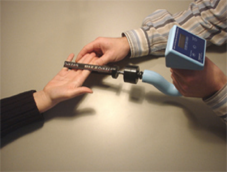
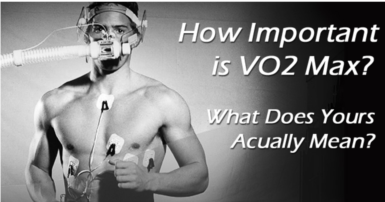
 Figure 1. Common strain gauge configurations for measuring axial (left) and bending (right) strains.


Since the inflation of the lungs will mostly cause axial stretching of the strain gauge, we will look at strain gauges that measure axial strain. When strain gauges are stretched axially, they are displaced. The strain gauge responds to strains with a change in electrical resistance. So, as strain on a strain gauge changes, so does the resistance in the gauge.

One common calculation related to strain gauges is the calculation for gauge factor (GF), represented by the equation:

This relationship can be used in our case to help decide which strain gauge to use in the strap design based on gauge factor, changes in length, and base resistance values in different strain gauges. In the case of our strain gauge strap, we are trying to determine how much strain the strap will experience and what ΔR will give the ideal sensitivity for the strap system. Thinking about the strap system, we can determine the ΔR range that we want the strain gauge to experience based on how sensitive to strain changes we want the gauge to be. As stated before, the gauge responds to strain with a change in resistance. This ΔR will change more drastically as more strain is applied to the gauge. During exercise, the body experiences strain from breathing, small strains from turning of the torso during movement, and other small strains from outside forces like bumping the strain gauge during movement. Given that the strains we want to register and record (strains caused by inhalation) are relatively larger than strains from external sources (strains caused by small movements or bumps), we want our strain gauge to be less sensitive to very small ΔRs and more sensitive to slightly larger ΔRs. And, by using the equation for GF from above, we can calculate estimated ΔRs with different strain gauges to decide on a strain gauge that fits our needs.

In order to solve this, we need to measure or estimate values for all other variables in the GF equation besides change in resistance. These values include:

  • Gauge factor: 2
    • Assumption: Common metallic strain gauges have a GF = 2
  • Length: 50 mm
    • Assumption: This is a large gauge size since strains due to inhalation are likely to be large
  • Change in length: 3 mm
    • Estimated: Based on a measurement of one shallow inhalation, the change in circumference of the torso on inhalation is 3 mm, meaning that the strain gauge will also stretch this much.
  • Resistance: 120, 240, 350 Ohms
    • Variable: These three resistance values are standard for the size gauge we estimate using

Now that we have all the variables needed to solve for the change in resistance, we can begin solving the problem!


Solve:

Of these three ΔR values, the value with the 120 Ohm resistance is the smallest, meaning this gauge is the most sensitive to strain changes. Given that we want a resistance that is not extremely sensitive, one might argue that the 120 Ohm gauge may be eliminated from the options. However, none of the above solutions have ΔR values that are extremely sensitive, so it can be concluded that none of them will be hypersensitive to false strain readings. If anything, the gauges will not be sensitive enough to properly differentiate between shallow and deep breaths. Since the 120 Ohm gauge has the lowest ΔR, it is the most likely to accurately indicate subtle changes breathing patterns. The 240 and 350 Ohm gauges have higher resistance change values, meaning they might not be as sensitive to resistance changes caused by strain and may not be able to identify shallow breaths. Therefore, we can say that the gauge that best fits into our parameters is the 120 Ohm gauge.

This solution is somewhat sensible in that the assumptions are reasonable. All assumptions made for this problem represent legitimate conditions that could be experienced in a generic user population. However, while this is a reasonable solution, it is important to note that this is not an absolute solution. The assumptions made in this problem are not necessarily representative of all real-world conditions. For example, the ΔL of the strain gauge may change between users based on different lung capacities and body sizes. Additionally, the strain gauge length may be different; in this problem, one gauge size was chosen, but there are many different gauge types that could have been used. And using a different gauge type will change the problem calculations, changing the resultant strain gauge choice. This problem as a whole is limited in that it is difficult to say which Ohm resistance value is the best without actually trying different resistors in the system and performing physical testing. And, this problem only considers the use of strain gauges; flexi sensors and other pressure sensors may be a more viable alternative given the large resistance change values calculated for these strain gauges. But, with the basic assumptions made in this problem, the solution is a fair estimate of which strain gauge to start the design process with. With the most appropriate gauge decided, work can continue on with the design of the strap system in an effort to help athletes understanding and monitor their breathing patterns.

For more information about strain gauges, visit:

Engineer Your Way to 10,000 Steps a Day

Many people are trying to get 10,000 steps or more in each day to become somewhat active. Whether getting in those steps will help to be healthy or active, the use of a pedometer will help to count those daily steps. Today it is hard for me to find a person who doesn’t have a Fitbit or other step counter on their wrist. So, what is their device really doing?

Fitbit Alta, a pedometer used to count steps, calories burned, and miles walked daily.

Pedometers use accelerometers to measure changes in velocity of the forces your body produces. The use of accelerometers is becoming increasingly popular in technologies for more than just pedometers. For instance, detecting car crashes to release the airbag, or turning off the hard drive when your laptop falls to prevent damage. There are many different features to consider when choosing the correct accelerometer for your specific application.

Accelerometer board designed to measure movement in the x, y, and z axis, another factor to consider when designing a pedometer. 

In the case of a pedometer, we want to know: how do we design an accelerometer to accurately count the movement of someone taking a step? We want the pedometer we use not to over count or undercount our steps. It needs to be sensitive enough to detect when we move enough, but not overly sensitive to count a sneeze as a step. There are many variables in an accelerometer to design it to your needs. In this case, adding a low pass band filter will help us to accurately count the steps we want.

In designing our accelerometer, we want to choose our maximum swing. This will be in the form of g, or acceleration due to gravity, 9.81m/s2. When measuring sudden stops and starts, you want a higher g, such as 5g. When measuring the earth’s tilt, only  1 is needed. Since we want to measure the movement of somebody walking, typically 2g is used.

The resolution of the accelerometer will determine how it will detect the smallest increment in acceleration. If you would like to improve the resolution, then you can do this by using a filter to lower the noise and bandwidth. The resolution can be given by the equation:

R=N x √(BWlpf x1.6)

Where R is the resolution, N is the noise density and BWlpf is the bandwidth of the output low-pass filter.

A few things to note: N is in the units µg/√Hz and the bandwidth is what we want to solve for to improve the resolution of the device. If I want to design an accelerometer with a 13-bit resolution, so that even low walking speeds are accurately measured, that would be the equivalent of an R value of 4mg. Based on high performance of pedometers with maximum swing of 2g, we will choose N to be approximately 120µg/√Hz.

Solving for BWlpf using basic algebra, we find that BWlpf=(R/N)2/1.6

Plugging in the values of R and N, we find that we want a bandwidth to allow for the frequency of about 695Hz.

Depending on the design of the accelerometer, there would be different values of N and R. For instance, certain companies may want higher resolution and may be able to get a different noise density based on their maximum swing and other factors. They would be able to choose the type of bandwidth filter based on their needs and adjusting the equation accordingly. The bandwidth of the filter used in designing the resolution of the accelerometer for a pedometer is just one of the many variables and problems an engineer would consider when designing a device to track steps.


Further Reading:

https://www.dimensionengineering.com/info/accelerometers

http://www.nxp.com/assets/documents/data/en/quick-start-guide/SENSORTERMSPG.pdf

https://help.fitbit.com/articles/en_US/Help_article/1143

Photo Sources:

https://www.fitbit.com/store

https://www.dimensionengineering.com/info/accelerometers

Force That A Resistance Band Needs To Withstand To Induce a One Gravity Environment

In space, astronauts need to work out about two hours a day to combat the muscle and bone density wasting effects of zero gravity. With no gravity, how are you supposed to workout? Don’t you need gravity to hold you in place to do a workout? Until the technology for artificial gravity is invented, NASA had to get a little creative to help astronauts workout. A harness with resistance bands attached to either side (pictured below) is used to hold astronauts in place to run on a treadmill. To most effectively reduce bone density loss, the resistance bands must produce enough downward force to simulate the gravity on Earth, a 1G environment. To choose resistance bands that are suitable for this purpose, you must know the total force that they need to withstand. So, how do you calculate the total tension in each band so that there is a 1G environment?

Astronaut running on TVIS treadmill with harness (left). Simplified diagram of the tension in the resistance bands attached at the hips.


Assuming that the astronaut is of average height and mass (H=1.77 meters, m=80 kg), we can determine the downward force the required for the 1G environment and how high the attachment point is (hips). According to the anthropometric data on the document attached (see bottom for links), we know that the height of the hips are 0.53 of his total height, equaling 0.9381 meters.

To determine what a 1G environment is we use F=ma (where a is the acceleration due to earth’s gravity, 9.8 m/s^2). So now we know that the force in the y direction must equal 784 N. Since there are two bands, each band is only responsible for producing half of that downward force, 392 N.

Before we solve for the tension in the band, we need to know the angle theta. Using simple trigonometry, theta = sin^-1(.9381) = 69.73 degrees. You can also use the width of the treadmill (.7 meters) with the height to find the hypotenuse and then use the Law of Sines to find theta. Either way will get you the same answer.

Now we have everything we need to solve for T.

T_y = T * Sin(theta)

T_y = 392 N (downforce),     392 = T * Sin(69.73)

T = 417.9 N.

This means that each resistance band must withstand 417.9 N of force to produce a 1G environment for a man who is 1.77 meters tall and 80 kg.

Assuming average height and weight is good because most astronauts are very close to the average height and weight of US males. There is not a lot of storage space on the international space station so multiple harnesses is not really plausible. By choosing resistance bands for average height and weight will be able to accommodate most astronauts adequately. I also simplified the body to a point mass, this changes the the angle of theta a little. In this application, I think this simplification is okay because it wouldn’t change the overall tension by a by much. A safety factor would easily cover the change in force that the angle is responsible for.

This information can now be used as a metric to select the proper material and dimensions for the resistance bands in the harness.

Below is a chart of the anthropometric data mentioned above, and my hand-written calculations for this problem.

Cycle Ergometers – Redesigning the Wheel


Monark Ergometer 879E [3]                                                                  Monrk Ergomedic 839E [6]

IDENTIFY

The basic principle of any ergometers is to measure the distance traveled in relation to an applied force to output the work that has taken to perform that task. This work outuput can be used to determine how much power has been produced and how much metabolic energy has been consumed [1]. Cycle ergometers are a common type of ergometers used for cardio-pulmonary exercieses and sports medicince diagnostic and performance testing which uses the task of cycling. When designing a cycle ergometer for repeated exercise usage it is improtant to think about what are the key components of the machine, the intended usage, how closely the machine can simulate road bike cyclig, storage, and the impact of that the device can have on the user and their exercice. An engineering problem in designing a cycle ergometer is determining the optimal size of key components like the wheel and thus the overall machine.

The motivation for this is that a smaller wheel allows for the machine to be more compact, lighter, and more portable allowing for greater home or clinical use

The unknown being solve for is the size of the wheel since this will give a known distance that the user has “travelled” per revolution and thus the equation for work (Work = Force*Distance) can be applied to find the unknown. The wheel is the main component of a cycle ergometer machine since it is the component that is being used to measure work output. Determining the optimized size of this wheel allows for adjecent compoenets to be appropriately designed so that the cycle ergometer is as compact as possible but still fully functional.

Question: Find the minimum diameter that the wheel can be in order to power the cycle ergometer at max applied force


FORMULATE

Figures:

Fig 1: Assumed forces acting on the wheel of the cycle ergometer

Background: Knowing what the minimum input wattage it takes to power the cycle ergometer, it is possible to use the conversion relationships for wattage and Kilojoules and Kilojoules and work to convert wattage into the minimum workout output needed to power the machine [1]. Knowing this then the equation for work can be used to determine the circumference and thus the diameter that the wheel needs to be.

Assumptions: the main wheel of the machine is a disc wheel with a mass of: 1.1Kg [2]

Based on previous cycle ergometer models the minimum power needed to power on the machine is: 156W at 60rmp [3]

The max applied force based on previous cycle ergometer models is: 12Kg [3]

The coefficient of rolling resistance (Crr) based on production bike tires at 31mph measured on rollers is: 0.005 [4]

Equations:

Unknowns: kilojoules (KJ), work (Kgm), wheel circumference (D), wheel diameter (d)

Knowns: Watt = 8W, seconds = 60s, coefficient of rolling resistance (Crr) = 0.005, Normal force (N) = 1.1Kg, applied force (F) = 12Kg, x = 60 rpm, time (t) = 1min


SOLVE

The first step in solving this problem is converting the minimum power input from Watts into Kilojoules so that it can be converted into the units for work.

Now that the kilojoules has been determined, the minimum input power can be converted into the units for work based on the relationship for kilograms per meter (Kgm) and kilojoules (KJ).

Since we now know the minimum work it takes to power the cycle ergometer, we can apply the equation for work to determine the circumference of the wheel.

We now have obtained the circumference of the wheel, yay! The final step in determining the optimal size and the answer to the question is to convert the circumference into diameter as follows:

From the calculations the minimum the wheel can be to power the machine at max applied force is 0.423m. This result is slightly smaller than the current common road bike wheel size of 0.7m in diameter [5] but still within a resonable range. This could be due to the impact of the assumptions made. It was assumed that the wheel of the cycle ergometer is a disc wheel which tends to be ligter than normal road bike wheels. It was also assumed that the coeficient of rolling resistance (Crr) was relatively high due to the assumed contact of adjacent component, which could impact the size since a smaller wheel takes less work to overcome the same rolling resistance as a larger wheel. Some limitations to this process are that it does not take into account of other acting forces other than applied force and rolling friction while also assuming that the user can cycle a minimum of 60rpm when this typically not physiologically possible for the typical user. While the calculated diameter is relatively smaller than current commercial road bike wheel, the calculated diameter is whithin a resonable range and so it can be concluded that the minimum wheel diameter needed to power a cycle ergometer at max applied force is 0.423m.


References:

  1. Egometer powerpoint by Dr. Robert Robergs at UNM
  2. Disc wheels at cyclinguphill.com
  3.  Monark Egometer 874E Manual, Monark Exercise AB
  4.  Rolling Resistances, Wikipedia
  5.  Common Tire Sizes at biketiresdirect.com
  6. Monark Ergomedic 839E Manual, Monark Sports and Medicine