
Click to enlarge
We started exploring plan reading in October with a look at stationing, a concept that some grasp easier than others. We tried to take some of the mystery out of stationing in that e-newsletter article (and have some good-natured fun with surveyors along the way). We’ll try to do the same with plan views here, but fair warning, the humor potential with plan views is very limited.
Construction plans are two-dimensional reflections of the engineering design for a bridge, a roadway, a curb ramp, a commercial entrance, or any other collection of transportation related elements. Various views are used in construction plans to stitch together the information that results from each perspective. We’ll take these views one at a time.
Click to enlarge
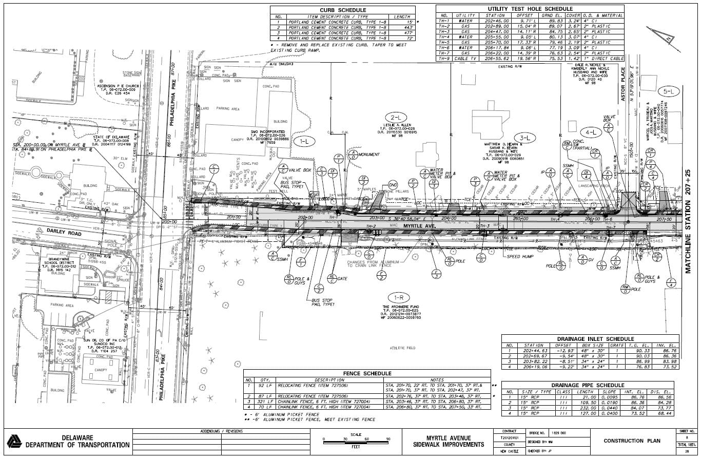
The “plan” view is commonly the first view we see in a construction plan set. This makes sense because, in addition to providing the basic horizontal locations of project elements, it often provides the basis for locating and orienting all the other views we subsequently see. Think of the plan view as a bird’s eye view of the project; in keeping with the flavor of the day, you can also think of this as a top down view from an unmanned aerial vehicle (drone).
The plan view often will occupy multiple sheets, using “match” lines to precisely show how the view on one sheet connects with the one on a subsequent sheet. For transportation related plan sets, stationing is the traditional navigational tool, and it usually leads along the centerline of the project or some other baseline. If you are new to stationing, our October e-newsletter article on the topic will get you up to speed.

Click to enlarge
Plan view sheets will often have supplemental notes, schedules, and tables containing specific information about storm drain inlets, pipes, guardrail, headwalls, and other elements.
Another view is the Sectional view or section. There are a couple types of sections, the first of which we are likely to see being the Typical Section. Whenever there is a continuous and consistent construction element, such as a roadway, a typical section is used to show the design. One way to visualize what the typical section is showing is to imagine you are standing down in a cross culvert trench (with appropriate safety measures in place) and able to look at all the layers of the roadway and underlying soils.

Click to enlarge
In the case of a roadway section, sections will usually be “cut” perpendicular to the stationing centerline and it shows us the various layers making up the pavement structure (the subbase soils, permeable treated base, soil cement, asphalt or concrete, wearing surfaces, etc.), underdrains, underground utilities (sewers, water line, conduit, culverts, etc.), roadside and median grading, guardrail, and so on. While used less frequently, the term crosscut or cross section is sometimes used in lieu of section.
A number of typical sections will often be shown, each applying to a certain length of the project, usually described with stationing. For the length of project where the typical section applies, the pavement and underlying aggregate and soil layers will be the same, the roadside slopes will be consistent, lane and shoulder widths will remain the same, and so on.
Typical sections are most often used to illustrate continuous elements, like a stretch of roadway. But sections are also used to slice open more discrete items, such as the stormwater inlet detail view shown here.

Click to enlarge
Detail views can be used for all kinds of discrete project items, such as inlets, manholes, headwalls, toe walls, rip rap outlets, soil erosion/sediment control practices, stormwater management practices, bridge elements (beam seats, diaphragms, shear stud spacing, parapet sections, etc.), and the list goes on.
Often, as in this case, the detail will include breakout details of its own, as well as sectional (or cross sectional if you prefer) views. So, unlike typical sections, these sections are usually very specific to a location and orientation of the item that is being detailed. In the stormwater inlet example shown here, Section A-A illustrates a cross section through the top slab in the location shown by the paired “A”s in the top slab drawing. Getting oriented with various sectional views in details can take a little practice, so start with easier elements and work your way up.
The final common view used is the profile. While a typical section is a cross sectional view of a roadway or other continuous element looking along its centerline, the profile is a cross section view perpendicular to the path of travel. Whereas with the typical section, you can imagine a view from a cross culvert trench, imagine for the profile view that you are crouching down in the roadside ditch and using your x-ray vision to view the layers of the roadway.

Click to enlarge
Profiles are excellent for illustrating the vertical curves and tangents of roadways, storm and sanitary sewers, water lines, conduits, underdrains, and so on. Normally, as seen in this example, the existing grade along the centerline is shown as a dashed line, along with the proposed finished roadway grade, revealing areas and extent of cut and fill. Again, the profile is keyed back to the plan view by use of project stationing – as you can see, stationing is about as basic a tool in construction plans as learning multiplication before you can understand calculus.
As you become more comfortable with construction plans and these various views, you may find that the plans begin to appear more three-dimensional as you instinctively match views together to visualize the finished product. Like anything you learn, your attempts will be clumsy at first, but in time a mental muscle memory will develop and you will find that becoming oriented with your first look at a brand new set of plans will come more naturally and more quickly.
Just about everyone in the transportation world encounters construction plans, at least from time to time. Many of us are intimidated at first, and if we are able, we may even try to avoid working with them, but in doing so, we risk being unaware of important details as they relate to our role in the project. Don’t outsource this – take time with each project to learn a little more about what the plans are showing and develop your skill set over time.
Another way to build your plan reading skills is to attend our Reading and Understanding Construction Plans, a half-day training workshop we offer once or twice a year, free to public agency personnel. And, while we’re shamelessly plugging our training, the best way to hear about these is to be on our distribution list, so use this link to get on it.
The Delaware T2/LTAP Center’s Municipal Engineering Circuit Rider is intended to provide technical assistance and training to local agencies and so if you have construction management questions or other transportation issues, contact Matt Carter at matheu@udel.edu or (302) 831-7236.
You must be logged in to post a comment.