Identify
Soft microfluidics revolutionized the development of sweat sensors by providing increased flexibility so the device can be worn on the skin while an individual is exercising. The material selected for these sensors is important for the flexibility and comfort of these devices. Elastomers with a low modulus but high elasticity are typically chosen as they allow the user to easily move while still obtaining sufficient sweat collection by close contact and flexibility upon the skin [1]. As these types of materials can more easily deform, it is important to consider the geometric design of these microfluidic channels. It is important the sweat sensor can withstand external forces or pressures, such as the individual touching the sensor, especially during exercise. These channels should not easily deform as significant deformation could greatly interfere with the volume of sweat collected, in addition to other measurements like sweat rate and the measured analyte concentrations.
It is important to first understand how externally applied forces influence the deflection of the microfluidic channels. We can then understand how the volume of these channels changes in response to applied forces which will allow us to select the optimal geometry that minimizes the change in volume to increase the accuracy of the device in realistic conditions [2]. If we want to account for externally applied forces that might be applied to the sweat sensor during use, should we design narrow or broad channels? Should there be considerations for height? To understand these questions, we will need to understand how the width and height ratio of microfluidic channels influences the percentage of volume change within these channels.
Formulate
To solve this problem, we will assume that the applied pressure acts as a uniformly distributed vertical load across the channel width. For simplicity we will only be calculating the results for a single channel, but the principles could be used to calculate the entire surface of the sweat sensor. Since the channels of sweat sensors are often rectangular, we will model the sweat sensor as a rectangular beam that is fixed on both ends. Once the sweat sensor is placed onto the skin we are assuming it is permanently in place as any movement of the sensor would ruin the obtained results. We are also assuming the channel has uniform thickness.
Figure 1. Cross section of microfluidic channel. For our calculations, L will be the width of the channel, h the height of the channel, and t the thickness of the channel. The channel length is a.
Figure 2. Channel free body diagram. Free body diagram of a beam fixed at both ends with uniform distributed loading applied [3]. L is the width of the channel.
Solve
The free body diagram of Figure 2 can be solved to find the vertical reaction forces at the fixed ends. By symmetry, the two vertical reaction forces are equal to the force of the distributed load which is the load times the length. Each vertical reaction force is equal to wL/2.
We can calculate the bending moment equation by making a cut in the beam to understand internal forces and moments and solve for the bending moment.
Figure 3. Cut channel section. In this figure, w is the distributed load, N is the normal internal force, V is the internal shear force, Mx is the internal moment at an arbitrary cut, FAX and FAY are reaction forces at fixed end A, and MA is the fixed end moment at A. Mx is defined in the positive direction and x is an arbitrary length along the total width (L) of the beam.
Solve for the bending moment equation:
The sum of the moments equals 0 and any horizontal forces do not create a moment about point A. As shown in Figure 2, the moment about a fixed end for a uniform distributed load is equal to wL2/12.

Calculate deflection:
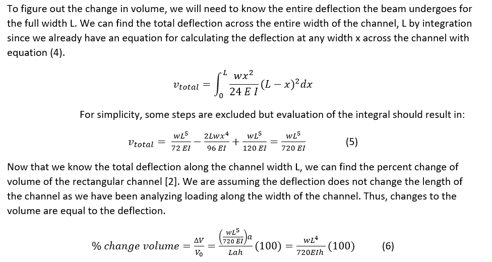
Calculate change in volume:
Equation (6) gives us the relationship between the width (L) and the height (h) of the channel so we can understand how the channel geometry influences the change in volume of the channel with externally applied forces. A positive change in volume is reasonable as our deflection of the channel was positive as well. These results were also found in a study analyzing colorimetric sweat sensors that found that narrow channels had a smaller volume change compared to broad channels [1]. There are several limitations to these calculations for practical applications. We analyzed the influence of deflection that caused a change in the height by vertical loading, but realistically the forces might have other components. Depending on how the sweat sensor adheres to the skin, the assumption of fixed ends may not always apply. There may also be instances in which the force applied is not uniformly distributed, but may act at a specific point.
Although the channel height is important to consider, the channel width is a much greater influence on the change in volume of the channel with deflection as it is raised to the fourth power. The height is only raised to the first power which has a less impact on the change in volume when considering external forces. We should aim to use narrow channels in the microfluidic channel design of our sweat sensor compared to broad channels as increasing the width increases the amount of deflection of the channel by equation (5) and produces a greater change in the volume of the channel.
References
[1]. Koh A, Kang D, Xue Y, et al. A soft, wearable microfluidic device for the capture, storage, and colorimetric sensing of sweat. Sci Transl Med. 2016;8(366):366ra165-366ra165. doi:10.1126/scitranslmed.aaf2593
[2]. Rogers, John, et al. Soft, wearable microfluidic systems capable of capture, storage, and sensing of biofluids. United States Patent WO2017218878 A1. United States Patent and Trademark Office. 16 June 2017.
[3]. Engineering Stack Exchange. Structural engineering – How to determine fixed end moment in beam? https://engineering.stackexchange.com/questions/15040/how-to-determine-fixed-end-moment-in-beam. Accessed May 14, 2020.


