
Many people are trying to get 10,000 steps or more in each day to become somewhat active. Whether getting in those steps will help to be healthy or active, the use of a pedometer will help to count those daily steps. Today it is hard for me to find a person who doesn’t have a Fitbit or other step counter on their wrist. So, what is their device really doing?

Fitbit Alta, a pedometer used to count steps, calories burned, and miles walked daily.
Pedometers use accelerometers to measure changes in velocity of the forces your body produces. The use of accelerometers is becoming increasingly popular in technologies for more than just pedometers. For instance, detecting car crashes to release the airbag, or turning off the hard drive when your laptop falls to prevent damage. There are many different features to consider when choosing the correct accelerometer for your specific application.
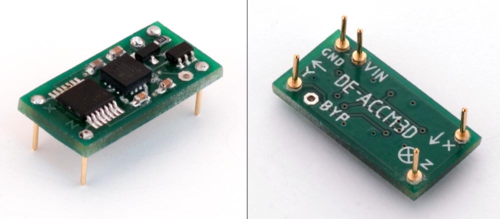
Accelerometer board designed to measure movement in the x, y, and z axis, another factor to consider when designing a pedometer.
In the case of a pedometer, we want to know: how do we design an accelerometer to accurately count the movement of someone taking a step? We want the pedometer we use not to over count or undercount our steps. It needs to be sensitive enough to detect when we move enough, but not overly sensitive to count a sneeze as a step. There are many variables in an accelerometer to design it to your needs. In this case, adding a low pass band filter will help us to accurately count the steps we want.
In designing our accelerometer, we want to choose our maximum swing. This will be in the form of g, or acceleration due to gravity, 9.81m/s2. When measuring sudden stops and starts, you want a higher g, such as 5g. When measuring the earth’s tilt, only 1 is needed. Since we want to measure the movement of somebody walking, typically 2g is used.
The resolution of the accelerometer will determine how it will detect the smallest increment in acceleration. If you would like to improve the resolution, then you can do this by using a filter to lower the noise and bandwidth. The resolution can be given by the equation:
R=N x √(BWlpf x1.6)
Where R is the resolution, N is the noise density and BWlpf is the bandwidth of the output low-pass filter.
A few things to note: N is in the units µg/√Hz and the bandwidth is what we want to solve for to improve the resolution of the device. If I want to design an accelerometer with a 13-bit resolution, so that even low walking speeds are accurately measured, that would be the equivalent of an R value of 4mg. Based on high performance of pedometers with maximum swing of 2g, we will choose N to be approximately 120µg/√Hz.
Solving for BWlpf using basic algebra, we find that BWlpf=(R/N)2/1.6
Plugging in the values of R and N, we find that we want a bandwidth to allow for the frequency of about 695Hz.
Depending on the design of the accelerometer, there would be different values of N and R. For instance, certain companies may want higher resolution and may be able to get a different noise density based on their maximum swing and other factors. They would be able to choose the type of bandwidth filter based on their needs and adjusting the equation accordingly. The bandwidth of the filter used in designing the resolution of the accelerometer for a pedometer is just one of the many variables and problems an engineer would consider when designing a device to track steps.
Further Reading:
https://www.dimensionengineering.com/info/accelerometers
http://www.nxp.com/assets/documents/data/en/quick-start-guide/SENSORTERMSPG.pdf
https://help.fitbit.com/articles/en_US/Help_article/1143
Photo Sources:
https://www.fitbit.com/store
https://www.dimensionengineering.com/info/accelerometers
