Glucose and Lactate are two analytes in sweat that would be highly desirable to apply sweat sensing technology to, each for their own individual reasons. Since the biosensing technology typically used to detect these analytes utilizes enzymatic reactions, temperature of the sample being tested must be taken into consideration when interpreting results due to its effects on enzymatic activity. Therefore, temperature sensors are an essential component of any sweat sensor that aims to give reliable feedback on either/both of these analytes. Multiple temperature sensing technologies exist, but a simple, commonly used technology is resistance temperature detectors (RTDs). These simple circuits use a Wheatstone bridge with a pure metal resistor that is exposed to the sample being tested. That resistor has a temperature-dependent resistance, and its resistance affects the voltage output of the Wheatstone bridge. In order to calibrate your sensor (a necessary process to ensure it gives accurate results), you must be able to use voltage outputs of known temperatures to identify the relationship between voltage and temperature. This problem will help us learn to do so.
Problem Statement
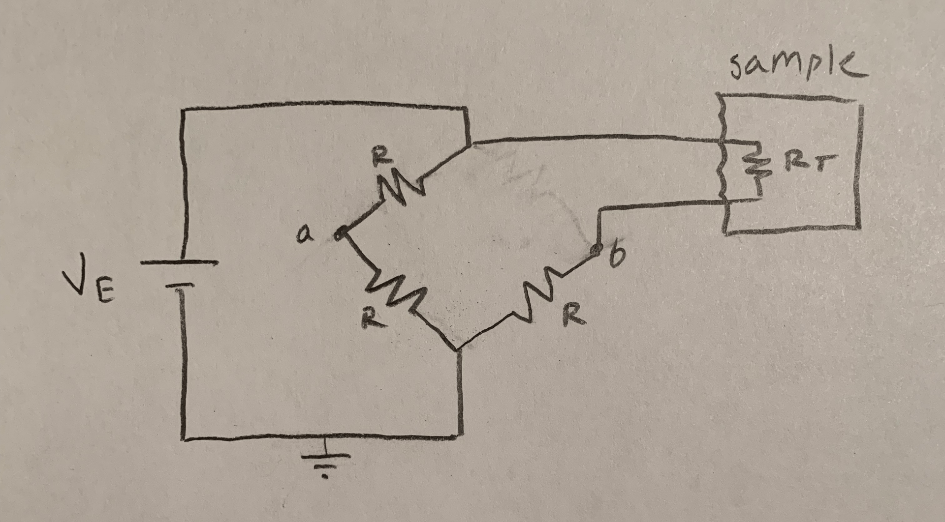
The Wheatstone bridge shown below (figure 2.) has four resistors, three of equal resistance R=10Ω and one temperature-varying platinum resistor RT. A voltage VE=1V is provided to the system by a battery as shown. Vo is defined as the voltage difference between points a and b, and is given by the general Wheatstone bridge equation provided below (figure 1.). Resistance RT is given by RT = R0(1+α(T-T0), where α is the temperature coefficient of platinum, α= 0.00385/°C. Given that R0= 10Ω and T0=0°C…
a. Write an equation for Vo in terms of T
b. Find Vo at T=20°C, T=30°C, and T=40°C
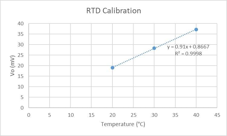
c. Devices aren’t always exact. Your RTD is giving values of Vo(20)=19.0mV, Vo(30)=28.3mV, and Vo(40)=37.2mV. Plot these values and find a line of best fit for your RTD (assuming linear relationship*)
d. Find the voltage Vo that would be expected at T=37°C
*Assumptions:
- Linear relationship between Vo and T- RTDs display much more linear behavior than thermocouples. They are not exactly linear, but for the purposes of this problem and learning how to calibrate, it is a fair assumption. It will cause the most error in the middle of our range of estimation, due to the parabolic nonlinearity of the true relationship between Vo and T. [1]
Solution
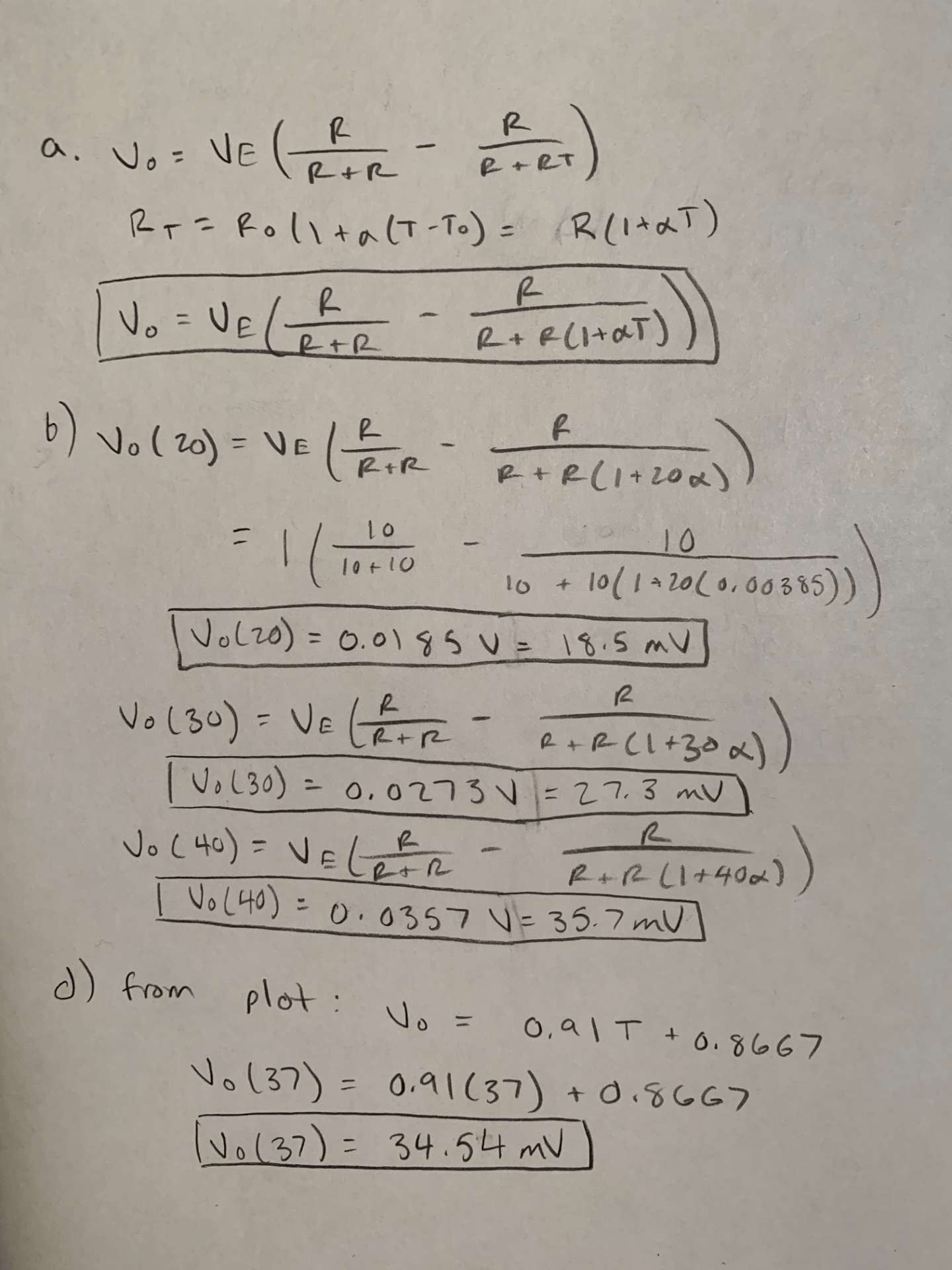
The algebra for solutions to parts a, b, and d of the problem are provided in figure 3. The plot for part c, created in Excel, is provided in figure 4. This plot was created by creating a column of temperature data and a column of the corresponding voltage data given in the problem statement for part c, highlighting those two columns, and creating a scatter plot. A line of best fit was added to the plot, and the equation for the line was displayed on the graph itself. Excel makes linear approximations for data sets like these very easy. While the linear approximation may not be the best fit for our data set, it appears to be very accurate, with an R2 value of 0.9998. Our final answer for Vo at 37°C makes sense, given that 34.45mV is between the values for 30°C and 40°C, 28.3mV and 37.2mV, respectively, and closer to that of 40°C. The linear approximation we made is a limitation of this solution. For a sweat sensing technology that gives medically relevant feedback to the user, we would want our analyte sensing results to be as accurate as possible, which would involve a curve-fitting technique as opposed to a linear approximation for our RTD. With the linear calibration we performed, we could use the values of Vo received from our RTD to determine the temperature of samples between 20-40°C with a pretty high level of accuracy.
References
[1] Trump, B. (2011). Analog linearization of resistance temperature detectors. Retrieved from http://www.ti.com/analog-circuit/aaj-article.html


Interesting problem! Love that you brought in some content from BMEG330 and, our favorite, wheatstone bridges!