Electronics! Putting It All Together

Electronics! Putting It All Together


In deciding what components to use for the control system, we knew that we wanted to consolidate everything.  Here is a list of components that we obtained:

– Boards

  • SainSmart Mega ADK (Any other brand of microcontroller board should work, this board in particular was chosen because there are many more ports and we did not want to cram everything in a small space.)
  • Sparkfun MegaShield (This was chosen because the large prototyping space was useful in acting as the breadboard.)
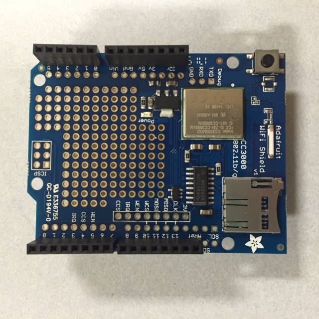
  • Adafruit CC3000 Wifi Shield or Sparkfun Electric Imp Shield – We chose the CC3000 (This is the medium in which our data would be transmitted to an online source such as Carriots.com. The Wifi shield is not a necessary if you would like to stream data.)
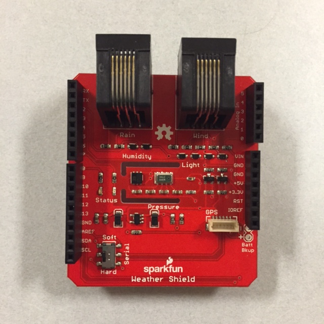
  • Sparkfun Weather Shield (This is the device that gathers the data collected with the Sparkfun Weather Meters. It’s necessary only if you would like to collect weather data to be streamed.)

– Other Components

  • Low-Flow Solenoid Valve Assembly (Refer to the blog post about the irrigation assembly for the exact pieces. The Solenoid Valve that we have is rated at 24 VAC.  A standard DC power adapter works well with this.)
  • 12 V DC Power Adapter (Preferably something rugged enough to be outside) (NOTE: Most boards are rated for a 12 or 15 V maximum input. Check your board specs for the maximum allowed voltage to be plugged into the power jack, or else the board will fry!  If a higher voltage is used, it must be isolated to the motor circuit only on breadboard.  Do not connect the 5V power strip to the motor circuit whatsoever.)
  • Sparkfun Soil Moisture Sensor
  • Sparkfun Weather Meters
  • USB Connector Cable
  • TIP31C Transistor (Other high current transistor should work)
  • Sparkfun Rectifier Diode
  • 330 Ohm Resistor
  • Three-port screw terminals
  • Header Pins (should come with boards)
  • Solid Core Wires

-Recommended Materials

  • Soldering Gun + Solder


Here are the instructions to set-up this entire assembly, according to each board/shield.
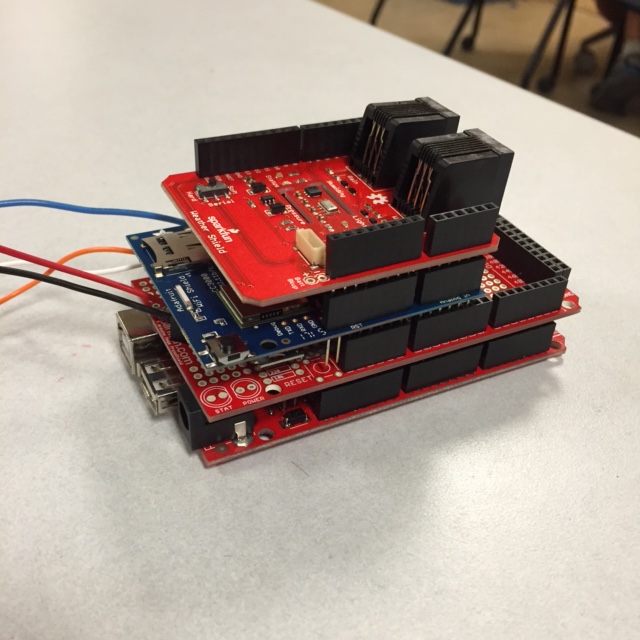
image1

-Sparkfun MegaShield

  1. This is where all the circuitry lies.
  2. Here is a wiring diagram of the solenoid circuit with the soil sensor:

circuitpicture2_bb

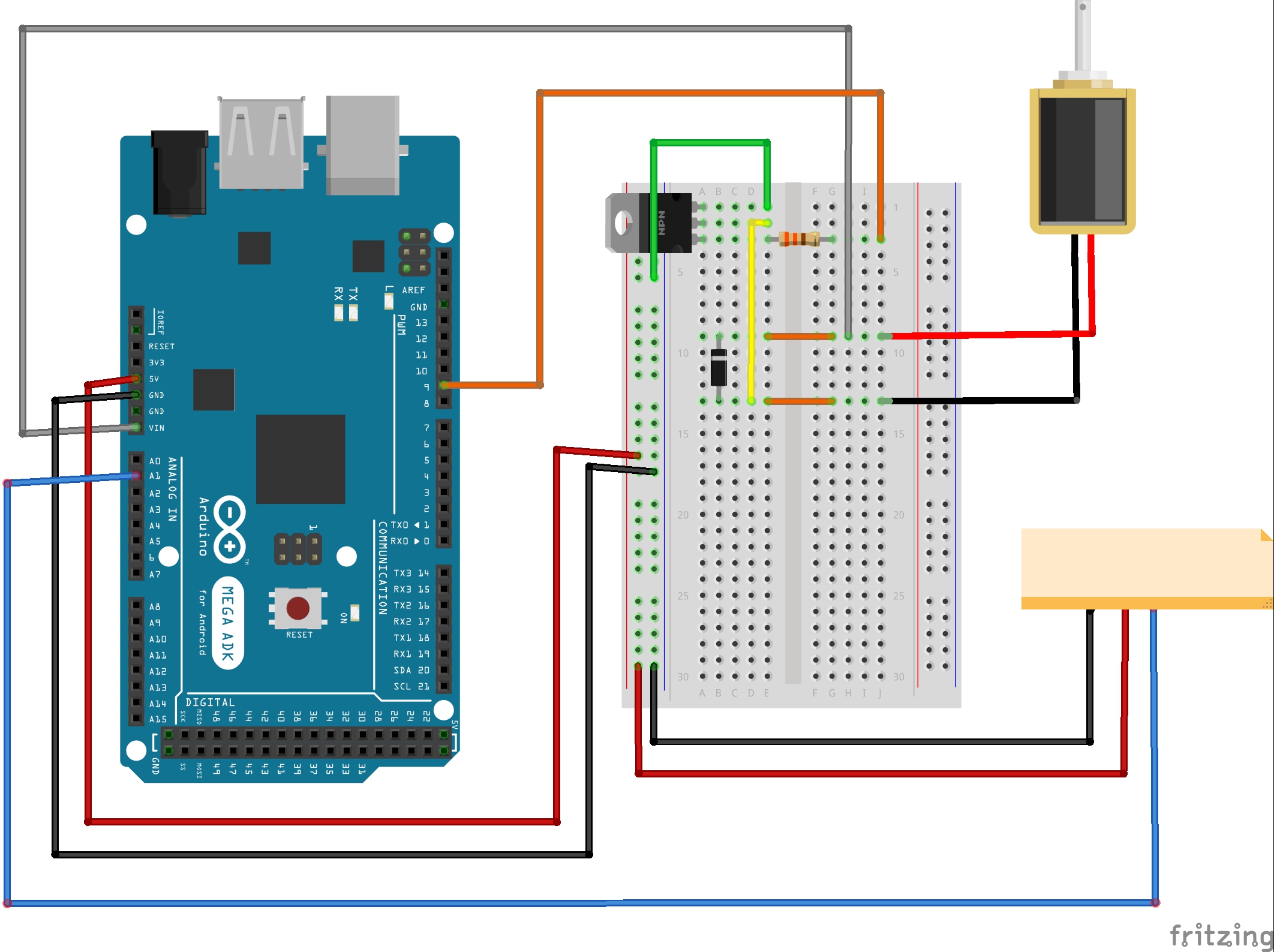
The little orange box above is the soil sensor.

This diagram displays all the crucial connections.  This can absolutely change depending on breadboard size and shape and available space.  For more soil sensors, use the next analog inputs as well as power and ground buses on the breadboard.

  1. With that being said, here are pictures of our prototyping shield, topside and underside, respectively. Before the components are soldered onto the board, the first thing that should be done would be to solder header pins onto the holes around the board, enabling the board to be stacked onto the main Mega board.

IMG_0804


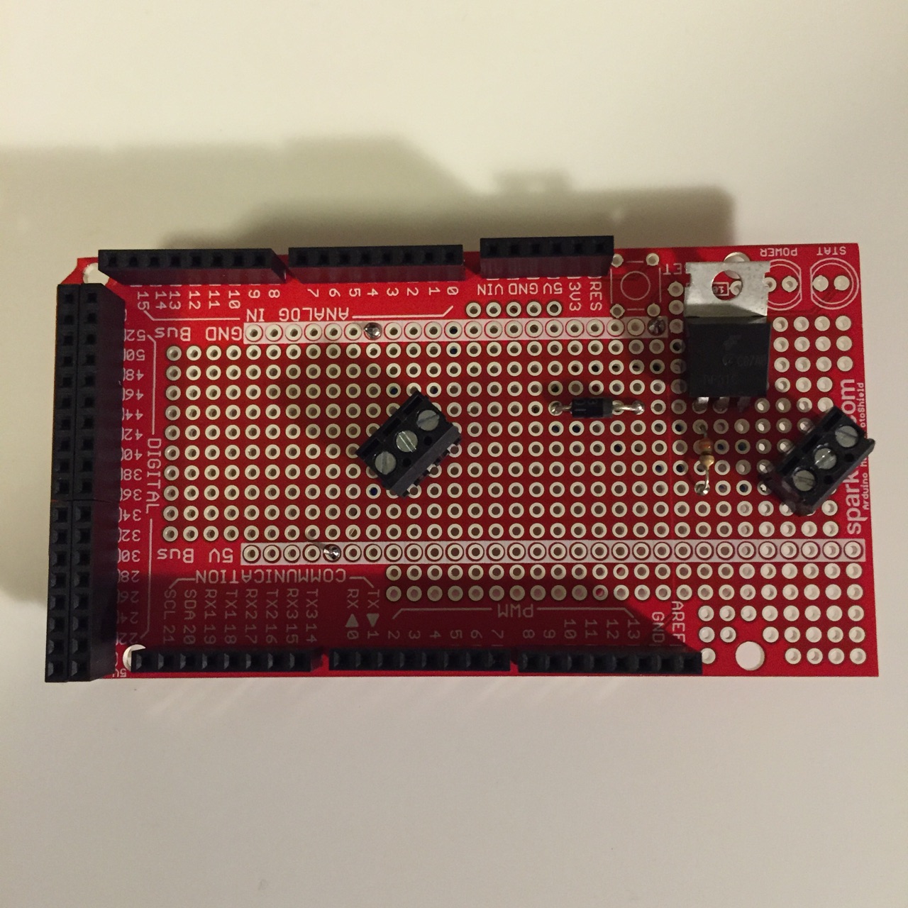
In the above photo, the screw terminal on the left is for the soil moisture sensor.  From left to right the ports go: VCC, Ground, and Signal.  The screw terminal on the right is for the solenoid valve. Use two slots for the wires and just let the third slot be empty.  For the solenoid valve and the soil sensor(s), solder on wires to suit your need.  Click here for getting started with the soil moisture sensor! This is a fantastic resource with links to other tutorials!

IMG_0805

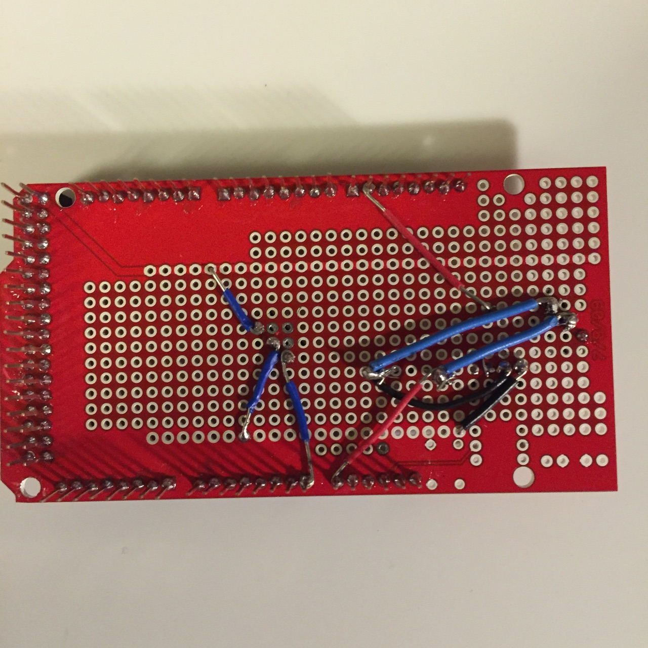
It is helpful to make a tiny hook in the wire when attaching it to a hole or pin in preparation to solder.


-Wifi Shield (Click here for Adafruit’s tutorial.)

image3

  1. Refer to “Wifi” blog post about setting up the wifi.
  2. Wifi shield stacks right on top of the MegaShield. Match up pin locations and stack onto corresponding postion.
  3. This produced much difficulty setting up, and therefore we are still in the process of getting this up and running with our live data. I would recommend reading this post in detail. Check back for future updates.


-Weather Shield (Click here for Sparkfun’s tutorial on how to create a personal weather station using this weather shield and Sparkfun Electric Imp Shield instead of the CC3000.

image2

  1. Refer to “Choosing a Weather Station” post about setting this up.
  2. This shield is connected in the same way as the others, in that it is to be stacked right on top, connecting the corresponding pin locations.
  3. This is also in the process of being set up. It is not difficult to get up and running, but it is interconnected with the wifi board and so it is still a work in progress.  Check back for future updates.


Code!

  • Here is the code to test the solenoid valve alternating between on and off (taken from Sparkfun Inventor’s Kit example guide code).

const int motorPin = 9; //this is the solenoid pin


void setup()

{


pinMode(motorPin, OUTPUT)


Serial.begin(9600);

}


void loop()

{

motorOnThenOff();

}


// This function turns the motor on and off like the blinking LED.


void motorOnThenOff()

{

int onTime = 3000;  // milliseconds to turn the motor on

int offTime = 3000; // milliseconds to turn the motor off


digitalWrite(motorPin, HIGH); // turn the motor on (full speed)

delay(onTime);                // delay for onTime milliseconds

Serial.println(“motor on”);

digitalWrite(motorPin, LOW);  // turn the motor off

delay(offTime);               // delay for offTime milliseconds

Serial.println(“motor off”);


}


  • Here is the code to run the solenoid valve with input from the soil sensor (taken from the online open-source community).


const int motorPin = 9;


int thresholdUpper = 850;

int thresholdLower = 650;


//this threshold was calibrated based on subjective testing of soil moisture level using the soil moisture sensor


int sensorPin1 = A1;


//if more sensors are used, create more variables such as “int sensorPin2 = A2” , “sensorPin3 = A3” , etc.


void setup() {


pinMode(motorPin, OUTPUT);

Serial.begin(9600);

Serial.println(“Booting up..”);

}


void loop() {


String DisplayWords;


int sensorValue1;


//follow the same trend as above for more sensors. Add more variables changing the number such as “int sensorValue2” and “int sensorValue3”, etc.


sensorValue1 = analogRead(sensorPin1);


//follow the same trend as above for more sensors. Use variable definitions such as “sensorValue2 = analogRead(sensorPin2)” and so on


//If more sensors are used, you will want to specify when you want to irrigation to turn on.  Either create an average value variable or modify the if statement to an “and” or “or” statement.  For information on Arduino syntax, click here.


if (sensorValue1 <= thresholdLower) {

DisplayWords = “Dry, Opening Valve”;

Serial.println(DisplayWords);

digitalWrite(motorPin, HIGH);


} else if (sensorValue1 >= thresholdUpper) {

DisplayWords = “Wet, Closing Valve”;

Serial.println(DisplayWords);

digitalWrite(motorPin, LOW);


} else {

Serial.println(DisplayWords);


}


delay(500);


}


The links above lead to pages where hookup guides, troubleshooting information, and other project ideas can be found.


For further questions, leave a comment below.

Wifi

Our team had two goals regarding Wifi.  The first one was to stream our moisture sensor data online and the second one was to pull data from websites to incorporate into our Arduino functions.  Arduino is an open source computer hardware and software company.  It basically allows anyone to directly link their code with their circuit.  One example would be creating a basic circuit with an LED and a resistor and linking it to code that tells the LED blink every three seconds.  Arduino is a fun program that allows endless innovation on a do-it-yourself level.  Using breakout boards and equipment from SparkFun Electronics and Arduino, we attempted to write code that would basically do the following: If the moisture of the garden gets too low check online weather data.  If it is not going to rain within the next few days, weather the garden.  We were able to wire the circuit to open the solenoid valves and water the garden based off of our moisture sensors but ran into trouble using the Wifi.  There are many different options available to connect to Wifi.  You can use an Ethernet Shield, Arduino CC3000 Wifi chip, or Adafruit Wifi Shield.  We were able to connect using the latter two.

There are various tutorials available online at adafruit.com, sparkfun.com, adafruit.com, and wunderground.com (Weather Underground) that will help anyone learn cool projects using circuitry.  When attempting any tutorial I recommend you read everything there is to read and not try to speed your way through anything.  Being new to Arduino coding and C/C++ I ran into many syntax coding errors while trying to create a functional code for our circuits.  Some tutorials you will find start with warnings as to what versions of code they are compatible with.  At one point I had to install a more outdated version of Arduino to be compatible with code that wouldn’t run on the newest version.  The tutorials you will find at these websites are generally helpful but the code they post does not always run as smoothly as one might like.  Adafruit has a great forums page and many dedicated administrators that I stayed in contact with as we tried to troubleshoot our coding.

Most of the problems I dealt with arose from working with many different products and websites.  When trying to stream data online we attempted to run data from a SparkFun moisture sensor through an Arduino UNO board with an Adafruit Wifi shield onto Carriots’ data streaming website (Carriots.com is a free application development website).  The syntax of the code changes depending on what kind of Wifi shield you use and then we had to form a string of data that Carriots could pick up.  I found different tutorials with free code for different steps of the procedure, and with help from Professor Roberts, starting combining the relevant parts of each tutorial code into one master sketch (a sketch is a page of code in Arduino).

For those just starting Arduino I recommend reading through Sparkfun’s basic tutorials before trying to take on any Wifi elements of this project.  Experienced Arduino users should try and follow our footsteps in creating an effective Wifi based garden watering system.  Below are some tutorials and forums that guided me in this research.


Soil Moisture Detector in Arduino


Parse Extract Weather Data for Arduino with Ethernet Shield


How to connect to a Weather Station/Weather Underground with Arduino (Ethernet)


Google Weather on Graphical Display with Arduino


Weather Station Wirelessly Connected to Weather Underground


Forum on Weather station data to Weather Underground Code Included


Make a Wifi Weather Station with Arduino and CC3000 Chip by “Open Home Automation”  (this is more sending data TO online)


Solar Powered Arduino Weather Station


Adafruit Wifi Weather Station


Sending Data to Carriots


Arduino Connection to Carriots


Arduino with Carriots Information


Predicting rain with pressure readings (related but not Wifi based)


Sensing Barometric Pressure with Arduino (related but  not Wifi based)


Similar Automatic Gardening Project with Arduino (states future goals to work with online data)

Creating a Plant Layout

The first thing to do when creating a garden layout is determining which plants you want to grow. Once you have found some plants, make sure that they grow well in your climate zone. Our garden is in zone 7. Try to choose vegetables and herbs that you cook with already, so that you will be more likely to use them around the house. A garden layout is dependent on a lot of things including, companion planting, lifespan, spacing, and other factors. We have created a chart that you can reference for companion planting. It tell which plants grow well nearby to each other and which do not. For the most part, we grouped perennials with perennials and annuals with annuals so that the annual planters can be tilled annually. Also some plants such as blueberries and squash take a lot of space to grow and this must be considered when planting them.

Designing and Installing the Irrigation System

Once we knew which parts we wanted to use to irrigate the garden, we then had to assemble them and lay them out in the garden. Teflon tape is needed when connecting plumbing parts in order to prevent leakages. Here is a video about how to use Teflon tape. Now the planters need to be filled halfway with the proper potting mixture that was previously discussed. Next, the hose needs to be cut to the proper lengths with scissors to fit the garden. This will depend on the shape of your garden layout. Be careful not to cut the hose too close to one of the drip valves. There should be 12 inch spacing between each hose and 6 inches of clearance from the edge of the planter as Rain Bird recommends. Then the hose needs to be fed through the holes on the side of the planters that were hole sawed earlier. After that the elbow joints, air release valve, water release valve, and zone control assembly can be slid into the hose. It takes quite a bit of force and is easier if you let the hose heat up in the sun first. The air release valve belongs at the highest point of the irrigation system. If your garden is flat, it does not matter where the air release goes. The water release valve can go at the end of the irrigation system. Be careful not to put this at a high point of the garden. Now the planters can be filled the rest of the way with potting mixture. You probably need adjust the position of the air release valve so that it is popping out the surface of the potting mixture. All that is left now is attaching the garden hose to the zone control kit.

Building A Planter

How to build a planter


For your rooftop garden you’re going to need something to hold your plants and soil mixture. For our project, we constructed 3’x3’ planters to enable us to implement the square foot gardening method. The sides are 1”x8” pine and each planter has a base made of plywood.


First, cut all wood to size.  We asked our local Home Depot to do this for us for the sides and plywood bottom because they did not fit into our car. This is a great option for anyone who doesn’t have the space or tools at home to do this step easily and safely.


We used size #8 x 2” wood screws to connect the four sides in a pinwheel pattern.

Screen Shot 2015-08-04 at 11.34.42 AM

(photo taken from All New Square Foot Gardening 2nd Edition)

Pinwheel patterning is when you overlap each board until you make a complete square. The holes for the screws were first pre drilled with about a 1/16 size drill and then the screws were placed.

IMG_8801

However, after filling the first prototype box with soil, the pressure became too much and started splitting the corners and wood around the screws.

 IMG_8787

So, for the second prototype we put in corner supports to relieve the stress on the sides. You could use metal corner brackets as well but we chose to go with wooden posts to keep costs down and allow us to use the same screws.

 IMG_8825 IMG_8823

The corner supports were attached to the planters with three screws on one side and two on the other. The support screws (gray screws in the image below) were placed in between the screws that were used to attach the planters’ sides together (gold screws in the image below).

IMG_8822

Secure the plywood to the bottom of the planter with three 2” wood screws on each of the four sides.

Screen Shot 2015-07-27 at 1.15.42 PM Screen Shot 2015-07-27 at 1.21.28 PM

After the bottoms are secured on the planters it’s time for the legs. Cut the legs from a 4”x4”x8’ pressure treated pine block. Cut the block every 4” so the legs are all the same height.

IMG_8797 IMG_8800

Place four of the legs a few inches in from each of the four corners and the fifth leg in the middle.

IMG_8821

Secure each leg to the bottom of the boxes with the same 2” wood screws.  On the inside of the planter, mark the location of the legs, and put two or three screws in through the plywood to secure each leg.

IMG_8820

After screwing in all 5 legs for each box you will need to use a ¼ size drill to put holes in the base of the planters to allow water to drain so the boxes (and plants) don’t rot. We drilled the holes in somewhat of a circle with eight holes around the outside and four in the middle. We also drilled two holes on either side of each corner support to help prevent wood rotting.


IMG_8633 IMG_8841


IMG_8839

(Finished layout and setup of the planter boxes)