 Reading plans can be daunting when you are starting out with construction projects. But, so was reading when you were still learning how to use a fork properly. First, you had to learn how to talk, then learn the alphabet, then you had to read those Sam Likes Jam books to get your feet wet. Before long, you could nestle into a copy of James Michener’s Chesapeake with ease, all 865 pages. The point is, you learn construction plans by degrees and you pick up various pieces over time. One of those that can stymie most of us at first is stationing. Let’s take the mystery out of it.
There are many parts to a typical road or bridge plan set that take some getting used to. There are plan views, section views, and profiles. There is a legend full of weird symbols. There may be earthwork summaries. There are endless schedules of barrier, pipe, stormwater inlets, and manholes. There will be stormwater ponds and other best management practices. There are construction details. There are detour plans and signing/striping plans. Sprinkled among many of these plans will be funny little numbers arranged as 7+00, 124+46, and even 1458+28.16. That is our topic for today and these strange number arrangements are stationing.
Think of stationing as a form of accounting, or coordinates, or directions. However you like, this is one of the ways surveyors locate very specific locations on the project site. Once you understand the format of it, you will see that it is very elegant, in a 1600s sort of way (the author hereby begs the pardon of all surveyors who were just insulted – surveying is an admirable, complicated, and precise exercise involving mathematics and possibly wizardry – we make fun only because we can’t do it). Surveying itself goes back to something on the order of 2700 BC with the Great Pyramid of Giza (seriously). Early on in the construction of linear infrastructure, like roads, the notion of chainage (derived from Gunter’s Chain, which equaled 66 feet; for homework, read more about Edmund Gunter to receive extra credit) came into play and chainage eventually became stations in our more modern vernacular.
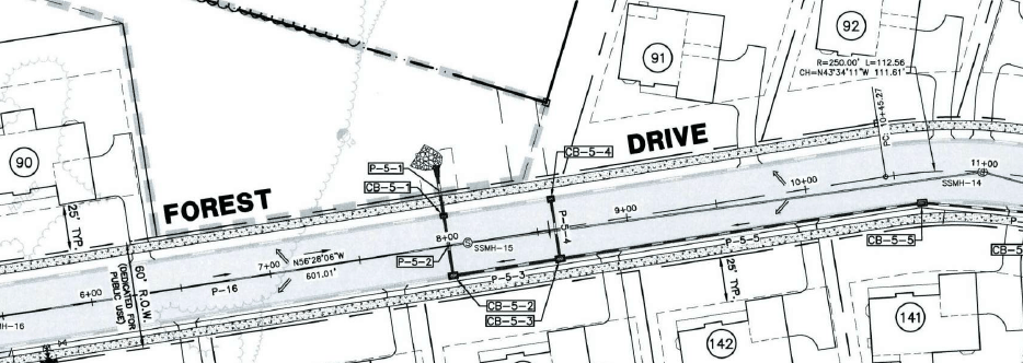
The best way to understand stationing is to look at relatively basic examples, so let’s use the residential subdivision street excerpt shown below to get oriented. Take a look along the center of the street you will see 6+00, 7+00, 8+00, 9+00, 10+00, and 11+00. These are stations. Congratulations, you just passed kindergarten. On to first grade.
A station is the horizontal measurement along the centerline (sometimes called the baseline) of a project. Distances are measured and points are identified on the plans with reference to station numbers. A highway station is one hundred feet. In its simplest form, the first station would be written as 1+00 and the second station would be written as 2+00. Station 1+00 and station 2+00 are 100 feet apart. In the plan view that we used above, we can do the same thing. Station 7+00 and station 10+00 are three stations apart – 300 feet. You just graduated first grade. See? This is easy.
Much like learning long division, we’ll spend the next four grades doing a billion examples that make the same point. No, let’s not. Instead, let’s learn a trick. Good drafting technique always aligns the plus mark in the station offset from the exact point on the centerline where the station actually exists. There’s also usually a tick mark on the centerline as well, like you see in the example plan section.
A second trick involves calculating the distance between two stations. Now, back in first grade, we used the simple example of station 7+00 and station 10+00, which are 300 feet apart. One way to make more complicated calculations easier is to remove the plus signs and just let these be 700 and 1000 – they’re at locations 700’ and 1000’ along the centerline – that seems more normal, doesn’t it (sorry surveyors). Well, 1000’ minus 700’ is 300’. So now, when we have to figure out how far it is between station 3+35.27 and station 16+22.56 (hang in there!), we can convert that to 1622.56 -335.27 and that equals (we can do this; we’re in the fifth grade for cryin’ out loud) 1,287.29 feet. We could do about fifty more example, but you get the point. You just graduated elementary school (and no, there’s not going to be a party or balloons or a clown or cake; it’s time to leave childhood things behind).
 Why do you need to know this – doesn’t the surveyor layout all this stuff? Yes, they do and you should be thankful, because the geometry and trigonometry they have to go through would give most of us a headache. But, the rest of us have to connect the dots on the plans for all kinds of reason, depending on the role we play, and you will find stationing all over the place.
For example, the profile excerpt to the right is all oriented to the stationing. For reference, let’s define a couple terms. The plan view above is a “look down” view – it’s what we would see if we were directly (perpendicularly) above that spot…or if we were looking at footage from a drone. Imagine instead that we had a plan view of a dining room table. The plan view would be fairly boring – a rectangle with slightly rounded corners. We wouldn’t see the legs because we can’t see through the table top. The profile view is like if we went over in the living room, sat on the couch, and looked at the table (assuming you have an open footprint to your living and dining areas and you don’t have to look through walls). Now you would see the edge of the table top, the legs, and the fork that someone dropped but forgot to pick up. That’s a profile view and that was summer school and you’re all caught up.
What do you see at the bottom of the profile view? Stations. There’s a bunch of other stuff (at the top you’ll see a bunch of stuff for the vertical curve that the surveyor will layout (praise), some sewer pipe, catch basins, stormwater pipe, the existing and proposed road grades, and so on), but that starts to get into what we talk about in our Reading and Understanding Construction Plans, a half-day training workshop we offer once or twice a year, free to public agency personnel. And, while we’re shamelessly plugging our training, the best way to hear about these is to be on our distribution list, so use this link to get on it.
 You will also see stations in many of the schedules. For example, the storm catch basin schedule to the right shows each stormwater inlet and lots of information about them. One key thing it shows is precisely where the inlet is located. The second structure on the list is CB-5-2, a 48”x30” concrete box with a top elevation of 62.42 (topic for another day) and so on, but you see that it is located at station 7+99.98. You also see an offset of 16.78R – what’s that all about?
If everything being constructed was on the centerline, things would be easier, but it doesn’t work like that. If you look back at the plan view you can probably locate CB-5-2 (use the stationing to get you there, really, really close to 8+00). You see if you look along the road towards higher station numbers (which you should always think in terms of), CB-5-2 is at the right edge of the roadway. In fact, the schedule tells us that the center of the inlet box is 16.78 feet to the right of centerline. In some plan sheets they will use positive and negative to denote right and left, respectively; here they have combined the methods, if you notice in the schedule. All kinds of things will be located with stations and offsets – hydrants, guardrail, manholes, property corners, pipe outfalls, etc. And that’s offsets and now you have graduated middle school. You understand stationing and you can go on to bigger and better things. We’re all very proud of you, but you’re still not getting a party.
We’ve had some fun with surveyors as we learned about stations but now you should be able to speak their language a bit better and understand plans a bit more. Come to the training and we’ll have some more fun with plans. The Delaware T2/LTAP Center’s Municipal Engineering Circuit Rider is intended to provide technical assistance and training to local agencies and so if you have construction management questions or other transportation issues, contact Matt Carter at matheu@udel.edu or (302) 831-7236.
You must be logged in to post a comment.