The Sports Gene Reflection – Malaria & Muscle Fibers

Class Make Up Blog 4/6 – Focus on Chapter 11

Throughout The Sports Gene Reading this week, I wanted to focus on the author’s thoughts on race and muscles fibers. He starts off by mentioning the physical differences between Europeans and Jamaicans. Studies have shown that Jamaicans have longer legs relative to body height and slimmer hips. This is backed by Bergmann’s rule saying that “humans with recent low latitude ancestry will also tend to be more narrow, with slimmer pelvic bones” (pg. 175). The point of these differences was to ultimately look at the reasons behind the running speed scales where both of these physical features proved to be beneficial. However, Epstein found a more anatomical approach by hypothesizing that “malaria in western Africa forced the proliferation of genes that protect against it, and that those genes, which reduce an individual’s ability to make energy aerobically, led to a shift to more fast-twitch muscle fibers, which are less dependent upon oxygen for energy production”. (pg 176)

Cooper found hope in this theory with a 1986 study from Laval University in Quebec published in the Journal of Applied Physiology. The scientists took muscle samples from the thighs of sedentary students , primarily from countries in West Africa. They took the same samples from two dozen sedentary white students  who were identical to the African students in age, height, and weight. The results showed that “a higher proportion of muscles in the African students was composed of fast-twitch muscle fibers, and a lower proportion was slow-twitch muscle fibers compared with the white students. Furthermore, these results showed that the African students had a significantly higher activity in the metabolic pathways that rely less on oxygen to create energy and that are engaged during an all-out sprint”. (pg. 179) This directly relates to the metabolic pathway topic review in class as we were discovering the differences between aerobic and anaerobic exercise. If the study showed that these students had metabolic pathways that rely less on oxygen to create energy, they may be more naturally inclined for sprinting since their bodies naturally choose an anaerobic pathway that doesn’t require oxygen.

In my opinion, I think this is an important study to look into as genetic factors can place people into categories where they may be more successful in certain sports. However, this chapter comments on several scientists who have no interest in investigating it because of the inevitably thorny issue of race involved. (pg. 185)  When our class held a similar discussion about the topic, it came down to whether you would want to know which sports you would thrive in as a child or merely have the freedom to choose your sport/activity based on your love of the sport. Would your parents be more inclined to steer their child towards a sport if they knew they succeed? A study by Lisa Guth showed that “A favorable genetic profile, when combined with an optimal training environment, is important for elite athletic performance; however, few genes are consistently associated with elite athletic performance, and none are linked strongly enough to warrant their use in predicting athletic success.” Therefore, it seems there are a difference of opinions on whether or not genes do play an important role in athletic success. Personally, if I had known I had the potential to be a star tennis player when I was young I would have pursued it. I would be interested to see how my own muscle fiber type relates to the success in certain sports and tweak my training based on that. However, to each his own. However, it seems there is a future of correlating athleticism with genetics that may even change the way we look at sports one day.


Sources

David Epstein, The Sports Gene. Chapter 11, Pages 175-185.

Genetic Influence on Athletic Performance


Barbells: Withstanding the 1,000-lb Deadlift

Identify

Barbells have been used for strength training for centuries, and the basic design of those used today was invented in 1928, yet they remain one of the most popular and effective exercise tools out there. From the main power lifts of bench, squat, and deadlift, to the olympic lifts of clean, jerk, and snatch, and limitless other movements, a barbell can be used to target any muscle group to improve strength and power. However, it must retain its shape. Through countless loading cycles, years of use, and sometimes extreme bending stresses, a barbell needs to be ready to be picked up and used again right away, and that means it cannot yield, or permanently bend – this would make it more difficult to use, change its motion patterns, and put it at risk of breaking. While typical use of a barbell for most people would not push it to its mechanical limits (Figure 1), those who compete in weightlifting often place so much weight on the ends of the bar that it indeed bends very much (Figure 2).  A barbell must be constructed of the proper material to withstand the loads it is placed under and bend without becoming permanently bent – or, in engineering terms, deform elastically but not plastically.

Figure 1. Use of a loaded barbell to perform a deadlift

Figure 2. Use of an extremely heavily loaded barbell to perform a deadlift

Formulate

When it comes to competition weightlifting, there are actually different dimensions and specifications required of barbells used for different lifts – read about it here. I decided to focus on a barbell for deadlifting because it’s the movement that can be done with the most weight and is not dynamic like olympic lifts. I borrowed dimensions from the most commonly-used barbell for deadlifting, the Texas 7-1/2″ Bar (Figure 3).

Figure 3. Dimensions of the most commonly-used barbell made for deadlifting

I also decided to design for preventing yield failure rather than fatigue failure because it is a more pressing design concern; it would make more sense to constrain for yielding and optimize for fatigue life rather than the other way around.

The world record deadlift is 500 kg (1,102.3 lbs) by Eddie Hall, so I used a weight of 453.6 kg (1,000 lbs), as events involving more weight than this are so infrequent that yielding in that case would not be of particular concern. This weight is divided into two evenly distributed loads at the ends of the bar, treated as a point load at the center of the distribution, while the opposing forces act where the hands would be placed (I assumed this to be the middle of the knurled portion as seen in Figure 3) [Figure 4].

Figure 4. Lifting of a barbell designed as a beam deflection problem

However, the problem can be simplified to fit a common pattern of loading/support (Figure 5), allowing for a few simple hand calculations to find the stress in the bar. This requires ignoring the weight of the bar itself (which, because of its even distribution and relative lightness, is not crucial anyway) and placing the loads at the very ends of the bar. In the end these assumptions will skew the estimate towards a slightly higher stress, giving an even safer design constraint.

Figure 5. Beam ends overhanging supports & two equal loads applied at symmetrical locations – http://www.engineersedge.com/beam_bending/beam_bending7.htm

Solve

By calculating the bar’s moment of inertia, the distance from the neutral axis, and the section modulus of the cross section of the beam, the maximum bending stress can be found to be 587 MPa (Figure 6).

Figure 6. Simplified representation of a loaded, held barbell and calculation of stress

Therefore, the barbell must be made of a material with a yield strength greater than 587 MPa. A look at a plot of materials’ yield strengths shows that metals, ceramics, and composites are all possibilities (Figure 7).

Figure 7. A plot of different materials’ yield strengths compared to their densities (from the text Materials Engineering, Science, Process and Design by Ashby et. al, 2007)

Metals make the most sense, however, because of their density and ductility. Composites’ light weight means they would be difficult, or impossible, to make into regulation-weighted-and-dimensioned barbells. Ceramics are also very brittle, meaning they break before bending at all; it is usually safer for a product to give warning before breaking, in the form of bending, making a ductile metal a better choice. Given its cost compared to titanium alloys, steel is easily the best choice for a barbell.

There is a dizzying amount of different steel mixtures and grades, but based on searching through tables and information sheets such as this and this, it is a safe bet that molybdenum-alloyed steels (steel alloy 4140/4340, yield strength 655/852 MPa) , cold worked austenitic stainless steels (stainless steel grade 301/304/310, yield strength 470-1310 MPa), and martensitic stainless steels (stainless steel grade 410/420/431, yield strength 415-1895 MPa) are all appropriate choices for a barbell that would not suffer permanent deformation even under the most weight a human has ever (dead)lifted.


Products recalled for children’s

Identify

Many furniture was designed harmful for children, many children were injured or killed due to tip over of the furniture. Dressers designed like this (fig. 1) has killed 7 children and got many injured. In 2016, IKEA recalled many dressers that have potential to tip over while kids climbing it. For a 8-year-old child, is it possible to tip the dresser over when climbing? Unknown: sum of the moment at the center of tip-over.


(fig. 1: dresser tip over due to defect)

(fig 2: information of one of the dressers IKEA recalled in 2016)

Formulate

Goal: find the moment at point O.

Formula to use: M = F*d(perpendicular)

The dresser is 134 cm tall, and 48 cm deep. Width is not necessary to measure since we are using a 2-d model.

First, we set up a 2D model to solve the problem (fig. 3).

O: point of tip-over. A: center of mass of the child. B: center of mass of the 3 drawers inserted. C: center of mass of the dresser (without drawers). D: center of mass of the top drawer that is out.

Drawers are 9.25 kg each. Dresser without drawer is 35.97 kg. Mass of a 8-years-old child: 23 kg. A(-55, 75), B(24,50), C(24,67), D(-24, 100)

Assumptions: the dresser is uniformed in weight. weight of the foots and top are negligible. No other things in the drawer. The top drawer is fully out and other drawers are fully inside. Center of mass occur at the geometric center of the main body.

(fig. 3 2-D model for the problem.)

Solve

ΣM= 28 kg* 9.8N/kg* -0.55m+3*9.25kg* 9.8N/kg* 0.24m+35.95kg* 9.8N/kg* 0.24m+9.25kg* 9.8N/kg* -0.24m = -150.92+65.27+84.56-21.76=-22.85N-m

The answer implies that a 8-year-old child is able to tip the dresser over by climbing on the top of the drawer. We assumed that the dresser is empty, and uniformed in weight. However, in real-life the problem could be more specific. Also we simplified the problem as a 2-D problem which implies that the dresser would only tip to the left, but in 3-D world the it could tip at any angle. Further, only one case which the child hangs one the top drawer with other drawers inserted was analyzed, but many other situation could happen in real-life.

The answer is reasonable since all values used were real-life values, and that is why the products were recalled.

In this case, any child weighs over 26 kg has potential to tip over the dresser and get injured or killed.

links:

http://abc7chicago.com/family/safety-group-highlights-recalls-of-childrens-products/1833068/

https://www.disabled-world.com/artman/publish/height-weight-teens.shtml

http://www.ikea.com/gb/en/products/storage-furniture/chest-of-drawers/brusali-chest-of-4-drawers-white-art-20252742/

http://www.ikea.com/ms/en_CA/pdf/Recalled_Chest_of_Drawers_Jun29_EN.pdf?icid=itl|ca|en_secureit_pdf|201606282141595720_1

Increasing the Accuracy of Wearable Heart Rate Monitors

Identify: Many people today look for ways to track their workouts to make sure that they are getting the best possible results whether it is for weight loss or training performance purposes. From high intensity interval training to slow jogging, heart rate monitors have proven to be popular in assisting users with how well they are performing. Furthermore, there are different types of heart heart monitors that are on the market today including chest straps and wearables that have proven to be successful. However, each different type of heart rate monitor has a slightly different method of measurement. So, lets take a peek into how these devices work.

Chest straps are one of the most popular and well known forms of a heart rate monitor that is used today. These straps use a wireless sensor to detect your pulse electronically and then send that data to a wristwatch-style receiver to display. Although these are deemed to be the most accurate, they are not the most comfortable to wear during a workout. Therefore, wearable wrist heart rate monitors have been developed which use an optical sensor built into the wrist unit’s watchband or case back to detect your pulse in a more comfortable way during your workout. The downside to these devices is that they are less accurate than a chest strap. Therefore, we can take a look into how to design an optical sensor that has the most accuracy possible for wearable HRM (heart rate monitor) devices.

Formulate: The main issues that have caused a lower accuracy and unclear signal in wearable HRMs have been the noise, weakness of the measured signal, amplitude of motion, and wide variance between different peoples’ wrists. To look into resolving these issues, it needs to be understood how these devices work. Optical HRM sensing is based on the principle of photoplethysmography (PPG). This allows the wristband to relate the pressure pulse from blood vessels as blood is passing through to each time a heart beats to get the heart rate. The way it does this is by using an LED to emit light into the body’s tissues and and use photodiodes to measure the amount of light that passes through them. The difficulty with this technology is that the measured signal is very small. In order to make a more accurate heart rate monitor, we want to be able to record the signal with the least amount of noise around it due to motion.

The most effective way for reducing the noise is simply the position of the wearable HRM in reference to the skin. The band needs to be worn with a snug fit and maintain an unchanged position throughout a workout. In the figure below, you can see the different interference levels depending on the gap between the skin. On the left, there is more interference shown by more blue lines and on the right there is less interference due to the proximity that the sensor is to the skin.

It is also important to understand that there are other factors that can cause interfere with a wearable HRM to decrease accuracy. For example, wrist curvature, wrist hair density and color, and skin color can all affect an optical signal’s reading. Skin color is a factor of great interest due to the fact that it greatly affects the signal and requires a change in LED brightness. Between the physical gap and skin tone, both factors are large determinants of accuracy for a wearable HRM.

Solve:

In order to design an optical sensor. We will want to minimize the gap between the sensor and sin but also include a sensor that can accurately read a signal with various skin tones.

We can use this equation for photocurrent by breaking it into AC and DC components of the signal. Typically, there might also be ambient light present (AC + DC noise). However, “the DC component of optical noise is usually subtracted due to an ambient light measurement immediately prior or after the LED light on measurement, resulting in an effective signal of”:

Further Readings

Best Heart Rate Monitors and HRM Watches

Heart Rate Monitors: How to Choose and Use

How to design an optical heart rate sensor into a wearable devices wristband

LED – Based Sensors for Wearable Fitness Tracking Products

SFH 7050 – Photoplethysmography Sensor

Using Inverse Dynamics to Prevent Ankle Injuries

Identify:

Ankle injuries are one of the most common injuries that occur in NFL linemen. If these injuries persist, the number of games missed can accumulate and the injuries can potentially end a player’s career. Research is currently being done to figure out how these injuries occur in order to design more efficient equipment such as ankle braces and modified cleats. One common method of injury involves the linemen planting the tip of their foot on the ground with great force. The force that is applied translates over to the ankle which causes the injury. Can we use engineering principles to approximate how much force is applied to the ankle? Yes we can, with the use of inverse dynamics. Inverse dynamics calculates forces and moments at one body segment by using the forces and moments of an adjacent body segment as well as the position, velocity, and acceleration of the connected body segments. By using inverse dynamics, one can solve for the amount of force that is applied to the ankles and potentially create new technology, such as insoles for the cleats, which can absorb some of the force that is applied and thus reduce the risk of injury.

Formulate:

Known Values and Assumptions:

Height = 1.956 m (6 foot 5 inches)* → length of foot (d) = (1.956)(0.0425)** = 0.08313 m

Mass = 141.521 kg (312 pounds)* → mass of foot (m) = (141.521)(0.0143)** = 2.024 kg

Force due to gravity (Fg) = m(9.81) = (2.024)(9.81) = 19.855 m/s^2

Normal force (FN) and force of friction (FFr)***, which are applied at the tip of the foot.

Angle between foot and playing surface (θ) = 15°[1]

Linear acceleration (a) and angular acceleration (α)****

Moment of Inertia (I)

Center of mass = (0.50)(d) = 0.0416 m

*Average height and weight of an NFL lineman during the 2015 season[2]

**Body segment weight and length[3]

***Exact value of FN and FFr can be used if force plate data is available

****Exact value of a and α can be used if motion capture data is available

Unknown Values to be Solved For:

x-direction force applied to the ankle (Fx, ankle)

y-direction force applied to the ankle (Fy, ankle)

Moment about the ankle (Mankle)

Equations to be Used:

∑Fx = max

∑Fy = may

∑M = Iα

Figure 1: Free-Body Diagram of the forces acting on the foot and ankle of an NFL lineman

Solve:

Step 1: calculate moment of inertia

Radius of gyration constant for the foot (Kfoot)[4] = 0.475 m

Radius of gyration of the foot (kfoot)= (Kfoot)(d)[4] = (0.475)(0.08313) = 0.0395 m^2

I = (m)(kfoot) = (2.024)(0.0395) → I = 0.0799 kg*m^2

Step 2: solve for forces in the x and y direction

∑Fx = ma→ (2.024)(a*cos(15)) = Fx, ankle – FFrFx, ankle = FFr+ 1.955*a

∑Fy = may → (2.024)(a*sin(15)) = FN – 19.855 – Fy, ankleFy, ankle = F– 19.855 – 0.524*a

Step 3: solve for moments

∑M = Iα → (I)(α) = Mankle + (dy)*(Fx, ankle – FFr) + (dx)*(F– Fy, ankle)

where:

d= y-distance between ankle or tip of foot to center of mass

d= x-distance between ankle or tip of foot to center of mass

∑M = Iα → (0.0799)(α) = Mankle + (0.0416*sin(15))*(Fx, ankle – FFr) + (0.0416*cos(15))*(F– Fy, ankle)

∑M = Iα → Mankle =(0.0799)(α) – (0.011)*(Fx, ankle – FFr) + (0.040)*(F– Fy, ankle)

The solution seems reasonable in the sense that forces are being added on to the ankle. The extent to which the forces are added will depend on multiple factors such as the angle between the cleats and playing surface as well as the height and weight of the athlete being tested. One limitation in this solution was not using exact values of angular and linear acceleration as well as the normal and frictional force. If one is able to accurately obtain these measurements via motion capture and force plate data, they can plug the values into the solutions above to determine exact values of the forces and moments acting on the ankle. For future studies it may be interesting to look at how the other lower limbs, such as the knees and hips, react to translated forces which can accumulate and potentially lead to a greater risk of non-contact injury.

Sources:

[1]: https://www.google.com/patents/US3413737

[2]: http://www.businessinsider.com/nfl-offensive-lineman-are-big-2011-10

[3]: http://www.exrx.net/Kinesiology/Segments.html

[4]: http://health.uottawa.ca/biomech/courses/apa2313/bsptable.pdf

Exercise and Save Money: Turning Exercise Work to Electricity

IDENTIFY:


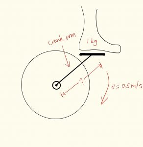
Cycling is a type of popular cardio exercise that can be widely seen in gym, home, and outdoor. This exercise allows exerciser to expend energy by rotating feet around the center of flywheel. Generally, the work done by exerciser just transfer to heat and lost in the air, but can we store the energy and utilize it for our daily life? The answer is yes. In article These Exercise Machines Turn Your Sweat Into Electricity fromIEEE spectrum, it states that Harr, a 21 year old mechanical engineering graduates of University of Florida developed that energy conservation device [1]. By converting workout energy to electricity, electrical bill can be reduced. At the same time, it encourages people to do more exercise to achieve a healthier life. In order to make a real cycling machine to meet this demand, engineers need to identify, formulate, and solve problems. For example, a question would be how long the crank arm of  the cycling machine should be in order to generate 6000 Joules energy in a hour (100watts) ? This question need to be solved because it makes more sense if the machine can generate noticeable amount of energy. The unknown is the crank arm length, and variables are rotating speed of exerciser and exercise duration, which can be assumed as 0.5 m/s and 1 hour, and the work expected is 6000 joules. By solving this problem, engineers would be able to design the machine with proper crank arm length.

Figure 1[2]This picture express someone is recycling workout energy to lighten bulbs.


FORMULATE:

Figure 2. This hand drawing express the flywheel and crankarm park on a normal bike.

Assumptions and Simplification:

(1) The weight of the exerciser’s feet is 1kg (Assume 70kg*1.45%*2)[3]

(2) exerciser’s feet are rotating in a constant speed of  0.5 m/s

(3) The generated energy expected in 1 hour is 6000J (100 watts)


The problem is to solve the length of the crank arm of this cycling machine (the radius of this circular motion).


Equations for circular motion and work: 

SOLVE:

Since we expect work done is 6000 Joules in a hour, and distance is 0.5 m/s *  3600 s = 1800m,

F = W/d = 3.3 N

F = 3.3 N = (mv^2)/r = (1kg*1m^2)/r

=> r= 1kg*m^2/3.3 N = 0.3 m

Thus, as assumptions made above, the radius of the crank arm of the cycling machine should be about 30 cm, which is realistic.

The variables like feet weight (directly related to force applied on pedal), and rotating velocity can be various for different user. Thus the energy generate can be different for different user too. Generally, more force input the exerciser do, the more the energy generated, and faster the exerciser rotate their feet, the more the energy generated.

One major limitation need to be concerned for this design is that the energy generated won’t be 100% converted to electricity. Thus there is more problems need to be solve to make the conversion more efficient.

Overall, the length of the crank arm of the cycling machine should be about 30 cm in order to generate 6000 joules per hour (100 watts). The solved length is a reasonable value. The energy generated for a single cycling machine might not be a lot, but it can be a more significant number if the system is utilize by gym on multiple cycling machines.

Path forward: instead of a in home exercise device, it can be further designed as a portable energy conservation system attached to a real bike that cycling work can be conserved into battery. In addition, not only cycling machine, the energy recycling system can be applied on other type exercise machines with similar mechanism.

More to read:

Could We Use Exercise Machines As Energy Sources? 

In the Gym: Clean Energy From Muscle Power

These Exercise Machines Turn Your Sweat Into Electricity

There’s more to an exercise ball than you thought

Identify

Anyone who has ever been to the gym has most likely seen or used an exercise ball. They’re big, inflatable balls that many people use to help them facilitate exercise or to stretch. They’re good for strengthening your core and improving your balance. Incorporating an exercise ball into your daily workout will add a challenge to your routine. A lot of people may also use them at home due to the fact that they are very affordable and versatile. While they may seem harmless, there can be serious risks when using one. It is important to use the correct size ball based on your height in order to get the most effective workout. It has to be inflated properly in order to work correctly. An over or under inflated exercise ball will put you at a greater risk for injury. The biggest danger of an exercise ball is having it burst. Over-inflation, improper use, and excessive user weight are some common ways that the ball may burst. The first step in preventing an exercise ball from bursting is choosing the right material. The material needs to be able to support the user and keep the integrity of the ball. Some common materials are vinyl and plastic. It’s important to figure out the force that is being applied to the ball, in order to figure out the strength of the material needed. The material needs to have a high tensile strength to support the user and prevent the ball from bursting and injuring the user.

Example of Exercise Ball


Formulate

The first step is figuring out the appropriate size of the ball based on height. When sitting on the ball, your knees should be at a right angle and your thighs should be parallel to the ground. The average woman in the United States according to the CDC is 64 inches tall and 166 lbs (75.3 Kg). According to anthropometric dimensional data, the ground to her knees is .285 (Anthropometric data-197t3u3) of her height.

.285 * 64 inches = 18.24 inches

Proper size for an exercise ball based on height


This means that the proper exercise ball should be 18 inches in diameter or 46 centimeters.

To find the best material, we can calculate Young’s modulus based on Hooke’s Law. 


Hooke’s Law  

?= stress = Force/Area

E= Young’s modulus

ɛ= strain= Δl/l

Surface Area of Sphere = 4 * π * r^2

Assumptions:

  • Exercise ball undergoes elastic and linear response to force
  • All of the users weight is being applied over the top half of the ball
  • Assume the exercise ball displaces 1 inch when force is applied

Solve

?= Force/Area

Force = 75.3 Kg * 9.8 m/s^2 = 738 Newtons

Half the area of sphere = ½ * 4 * π * 9.12^2= 523 in^2 = .337 m^2

? = 738 N / .337 m^2 = 2190 N/m^2

ɛ= strain= Δl/l

Ɛ = 1 inch/18.24 inch = .0548


2190 N/m^2 = E * .0548

Young’s modulus: E = 4.00 x 10^4 Pa


From this calculation, an exercise ball would need to be made of a plastic or vinyl with a Young’s modulus of around 4.00 x 10^4 Pa.

The assumption that the user’s total weight is distributed on the entire top half of the exercise ball led to the Young’s modulus to be underestimated. In real life, the user’s full weight wouldn’t be on the ball and it would also be distributed over a smaller surface area. The actual material would have a higher Young’s modulus than the calculated value. 


Learn more about the things you can do with an exercise ball!

http://www.webmd.com/fitness-exercise/features/10-fun-moves-to-reshape-your-body-with-exercise-ball-workout#1

http://www.fitnessmagazine.com/workout/exercise-ball/best-stability-ball-exercises/

Exercise Balls – The Ultimate Guide


Physical Therapist’s Tool of Choice- Hand Held Dynamometers

Identify

For physical therapists, one of the most important and sometimes most challenging aspects of their job is to track patient progress during rehabilitation from an injury or surgery.  While most of this can be done based on patient reporting (such as 1-10 pain/discomfort scales) or qualitative therapist observations, they collect quantitative data whenever possible.   One of the most common ways therapists can document progress is through strength testing.  For larger muscles, such as the quad and hamstring, larger testing apparatuses, like the Biodex, are used to measure strength. These machines, however, are large and difficult to use. They can be oriented for smaller muscles but almost always therapists will opt for hand-held dynamometers. Over the years these dynamometers have developed from simple spring or strain gauge contraptions to sleek digitalized devices.

The RIHM (Rotterdam Intrinsic Handdynamo Meter)

Taheel Technology Hand- Held Electronic Dynamometer

The above dynamometers are used to test grip strength and for the sake of explanation I will focus on this orientation., It is important to note that clinics often use the device shown below to measure strength of the arm and shoulder region since it allows for measurements to be taken in many different directions. For example, knowing the internal rotation and external rotation strength of a baseball players injured arm in comparison to his healthy one will allow the therapist to decide when the player should be allowed to return to play.


As I mentioned, all of these devices are designed on the seemingly simple basis of springs and strain gauges, Therefore, when designing a dynamometers the starting point is to decide what spring to use. If the spring constant is not stable and known, the device cannot be calibrated and will not result in accurate readings.


Formulate

For a grip strength dynamometer the patient pulls on a a handle connected to a spring of a known constant. Based on the displacement of the spring from it’s resting position the force they generated can be calculated.  This force is a direct measure of grip strength.  To decide the stiffness of the spring that should be used an engineer must use Hooke’s Law:

Hooke’s law states that the force of extension on the spring is proportional to the displacement of the spring.

The following assumptions can be used to calculate the max spring constant that should be used:

  • Force (Fs)– According to a study done by Top End Sports the maximum grip strength the dynamometer must be able to withstand is 57.5 kg.
  • Displacement (x)- Based on average hand sizes it can be assumed that the maximum displacement of the spring will not exceed 9 cm.

Fundamentally, stiffer springs have higher spring constants. For this reason, we know that the spring constant should be minimized, yet must be able to detect the max force and displacement it may experience. You essentially do not want to make it harder than it has to be for the patient.

Using these two assumptions and an understanding of Hooke’s Law it can be determined what the max spring constant that will be needed.


Solve

The following steps are used along with the assumed values to determine the ultimate spring constant:

F=-kx

57.5 N=-k(0.09 m)

k=-638.889 N/m

According to these calculations, a spring with a constant below approximately 640 N/m will suffice in your design of a handheld dynamometer.

Now it is important to understand the implications of the assumptions made here so your design can be altered for maximum efficiency.  It is necessary to consider the patients that will be using your design.  While the calculations above are generalized for average sized patients this may not fit your needs. For example, if your device will be used by pediatric patients the assumed values can be much lower whereas if your device will be used by athletic trainers in professional sports, the numbers should probably be increased.

The development of such dynamometers has been on the rise as their clinical prevalence has also risen.  They are extremely beneficial to clinicians yet are based on such a simple engineering principle.

For more information on the benefits and design of dynamometry I encourage you to check out the following readings:

http://www.prohealthcareproducts.com/blog/handheld-dynamometers-and-manual-muscle-testing/

https://www.ncbi.nlm.nih.gov/pubmed/18796949

https://www.ncbi.nlm.nih.gov/pmc/articles/PMC2868792/

Wheel on Up, Pull on Down

Many common diseases such as Multiple sclerosis, Cerebral palsy, and Post-polio syndrome as well as traumatic brain and spinal cord injury, strokes, and tumors can lead to Paraplegia, or paralysis below the waist. While paraplegia of course is limiting, upper-body exercise and strength building is vital to establish an active, independent, healthy lifestyle. Exercise for those with spinal cord injuries and paralysis have also been shown to decrease the risk of developing many associated secondary conditions such as osteoporosis, cardiovascular disease, pressure ulcers, urinary tract infections, diabetes and arthritis. Exercising has also been shown to control pain, improve mental health, and maintain a healthy weight for those with limited mobility. However, the number of possible exercises are limited by a lack of accessible equipment and resources for people with limited mobility.

     Image 1. Diagram of muscle groups targeted by the lateral pull down machine.

An example of a piece of equipment that could increase upper body strength is a lateral pull down machine as shown above in Image 1. This machine is used in a sitting position and the user grasps the bar with palms facing forward and pulls the bar down toward their chest. This exercise targets the rhomboid major, latissimus dorsi muscles, located on the sides of your rib cage, the biceps, the lower trapezius, and the posterior deltoid in the back of the shoulder, all of which contribute to a stronger upper body.

Because this piece of equipment is composed of a bench and thigh stabilizer, someone in a wheelchair would not be able to use it to build their upper body strength without assistance to move out of their wheelchair. This is an issue for several pieces of upper body strengthening equipment. The question is, how could these pieces of equipment, the lateral pull up bar particularly, be altered to provide more independent access to those in wheelchairs without taking away from their current effectiveness? If this question were to be solved, perhaps it could lead those with limited mobility to feel more comfortable at community gyms and provide them with a means to exercise more independently.

Assumptions and Estimations:

  • Average arm length (young man with average height): 25 inches
  • Average armrest of wheelchairs: 30 inches
  • Height of resting bar combines the height of the armrest of the wheelchair and average arm length above, minus 5 inches to account for women as well
  • Average height of chairs: 19 inches
  • People perform pull down correctly and reach straight up to get bar
  • We are calculating force at hinge, each horizontal measurement to calculate moment is taken from this origin
  • Height of bench is 2 inches (measured at UD gym)
  • Height of stabilizer varies, but maximum would be 7 inches away (measured at UD gym)
  • Weight of bench is 5lbs
  • Weight of stabilizer is 1lb
  • Weight of each member is 6lbs

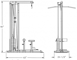
Image 2. Dimensions of standard Stack Loaded Lat Machine by Deltech Fitness, shows typical set up of the Lateral Pull Down Machine

As shown in Image 2 above, which is similar to most lateral pull down machines, the first aspect that requires adjustment is the dimensions. The width of the area where the wheelchair could pull in would have to be increased to a width greater than 32 inches in order to meet ADA standards for doorways. The bench and thigh stabilizer would also have to be adjusted so it could be cleared away from the area in which the wheelchair will sit. This machine can be altered by increasing the width to 33 inches and implementing a foldable bench/stabilizer mechanism that can be pushed up to the left or right side as shown below in Image 3a and 3b.

Image 3a (top) and 3b (bottom): 3a – Overlooking design of lateral pull down machine with updated dimensions that allow those in wheelchairs to access, as well as a removable bench that can be folded up. 3b – Image of bench and members in folded up position showing weight distribution centered around the hinge.

Using the following equation to determine moment on hinge:

|Mo| = (Force) * (Perpendicular distance)

and taking into account all assumptions and measurements used, the torque on the hinge can be calculated using the following values:

(Wbench*Distancebench) + (Wstabilizer *Distancestabilizer ) +(Wmember1 + Wmember2)*(Distancemembers)

(5lbs*20in)+(1lb*28in)+(12lb*9.5in) = 242 lb*in

The total torque on the hinge calculated is  242 pound inches. An off-set hinge made out of stainless can be used which provides a greater length on the ground to counter the force caused by the hanging bench. Reaching the bar is another issue for those in wheelchairs. To combat this issue, the wire can be lengthened so that the resting position of the bar should be 50 inches off the ground in order to provide access to those who are sitting without having to get up.

 This solution is assuming a standard size of wheelchairs which is used by the ADA when performing construction of doorways, however, wheelchair height and widths do change and not all will be able to fit in this gap. Exceptionally tall people may also suffer from these changes, as the wire length increase was done to help an average height or lower person. Those who are a lot taller may not gain full effectiveness of a pull down if they are starting lower than the top of their arm span reaches. This solution is indeed reasonable for those that have disabilities requiring the use of wheelchairs, however it is difficult to enact global changes such as this for development of equipment as the majority of users have the ability to use machines like this without these changes. Changes have to be encouraged by all to improve the accessibility to healthcare and exercise to all groups, even those who are marginalized. The value for the torque on the hinge makes sense, as it is carrying the full weight of the bench and the members that typically support the full weight of the user.

This solution may also need to be adjusted because sometimes gyms are limited in size and may not be interested in the fold up chair that could potentially take up more space than the original version. Coming back to the original question, this solution shows that equipment like the lateral pull down machine can be used for those who are disabled, and the development of this in gyms should be encouraged. Those with disabilities deserve the same opportunities to create a healthy lifestyle and feeling of community that comes with working out in a gym. The more independently they are able to do this, the more inclined they will be to continue. T changes in dimensions of the typical machine as well as the moveable bench allow that for those who typically would be unable to build their upper body strength in this way the ability to do so.

Additional Resources:

http://www.spinalcord.com/types-of-paralysis

https://www.ncbi.nlm.nih.gov/pmc/articles/PMC2694784

https://www.karmanhealthcare.com/how-wide-does-a-doorway-need-to-be-for-a-wheelchair/

http://www.livestrong.com/article/503333-what-are-the-benefits-of-a-lat-pulldown/


Designing Safer Cleats

Identify:

The earliest use of cleats has been reported since 1525 when King Henry VIII had a pair of soccer cleats. Since then, their design has changed drastically in order to accommodate changes in sports and technology. Today in sports there are many varieties of cleats that each provides their own advantages and disadvantages. However, as safety becomes a priority in modern sports regulation, certain cleat materials are beginning to become banned from use. Metal spikes present a hazard to players who may be stepped on or kicked. So there is a need for new cleats to be made from less hazardous materials that still provide the facilitation of rapid acceleration and deceleration in athletes.

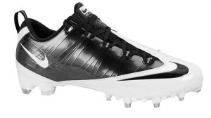
Figure 1: A low-cut cleat with metal studs.

When athletes accelerate or change direction there is a great deal of force that is placed between the shoe and the ground. In order to prevent slips, studs on the bottom of shoes are necessary so that greater amounts of force can be reached. These studs can be replaceable or permanently attached to the sole of the shoe. Depending on the amount of force, the studs must be designed with a large enough surface area of attachment to withstand the shear stress. By understanding how much shear force each cleat stud will experience, it is possible to design a shoe with large enough studs that will not break off of the shoe when the user is accelerating.

Formulate:

In order to design a cleat able to withstand the forces of athletes there are several factors to consider. The material that is being used in the design of this cleat is rubber which provides stability and strength without the dangers of metal studs. The force applied to the studs will be greater if there are fewer studs and smaller if there are more studs. The weight and speed of the user must also be considered for the design. Heavier and faster users will generate more force when they accelerate or decelerate. It is also important to consider which sport the shoe is being designed for as different sports deal with different sized athletes and different speeds. For this design the cleat is being made for soccer players. The heaviest soccer player currently in the league weighs in at 227 pounds. With regard to slowing down and speeding up, Usain Bolt can accelerate from 0 mph to 12 mph in 1.85 seconds. So with this known weight and acceleration data, assumptions and simplifications can be made in the calculations.

 
Figure 2: Depicts the force of the ground acting on the shoe in order to accelerate the athlete in the +X direction.


Figure 3: Fground is translated into each stud separately.

Assumptions, Simplifications, Estimations, and known values

Weight: 250 pounds (more than max soccer player weight)

Acceleration: 10mph in one direction to 10mph in opposite direction in 2 seconds (faster than Usain Bolt.

10 studs on the cleat (number used in many designs)

Force in Y-direction negligible

Shear modulus of rubber is 300kPa

Equivalent force applied to each stud


Equations used:

Force = mass * acceleration

Acceleration = change in velocity / time

Area of circle = pi * r2


Solve:

Solving for force applied on each stud:

20mph = 8.94 m/s

250lbs = 113.4kg

a= (8.94m/s)/(2s) = 4.47m/s2

F= (113.4kg)*(4.47m/s2) = 506.9N

F/stud = 506.9N/10 = 50.69N = 11.4 pounds of force per stud

Solving for radius required per circular stud

300kPa = 43.51psi

SA = (11.4lbs)/(43.51lbs/in2) = 0.262 in2

0.262 in2 = (3.1415)*(r2)

r = .288 in


Each circular stud will need to have a radius of at least 0.288 inches in order to withstand the applied shear force and not be torn off of the rest of the shoe. If a heavier weight, a larger change in velocity, a shorter time period, or fewer studs were used in the calculations, the required radius would be larger than the calculated value. This value is reasonable as it would easily allow for 10 studs to be configured onto the bottom of a shoe without the need for a larger shoe sole.

However, these calculations are limited in that the forces in the y-direction were left out. The force of gravity would compress the studs into the shoe in addition to a shear force. This may result in an increase or decrease in required radius of the studs. Additionally, this assumes that only one foot is involved in the process. If both feet are being used then more studs are being applied and therefore the equivalent force each stud experiences will be decreased. Knowing the required radius though will allow for the design of a rubber cleat that can be used in a similar way to metal cleats without losing any functionality.


For more information, visit:

http://www.goldenshoesmovie.com/the-history-of-soccer-cleats-part-1/

http://footballstopten.com/top-10-heaviest-footballers/10/

http://datagenetics.com/blog/july32013/index.html

http://www.engineeringtoolbox.com/modulus-rigidity-d_946.html