walking through the sky

Seating and treadmill exercise device

Patent Number: US7052441 B2

Patent Filing Date: Jan 23, 2004

Patent Issue date: May 30, 2006

How long it took for patent to issue: 2 years

Inventors: Mithra M. K. V. Sankrithi

Assignee: The Boeing Company

U.S. Classification: 482/54

Claims: 12

If you’ve ever been on a long distance flight you know the feeling of sitting upright for countless hours, not being able to stretch your legs. You try and walk up and down the aisle, but between flight attendants handing out food and drinks, passengers waiting in line for the lavatory, and people making conversation it makes it difficult to efficiently stretch your legs. What if you could take a ten-minute walk while 36,000 feet in the sky? This patent proposes to create a seating and treadmill exercise device for aircrafts that would allow passengers to stretch their legs and partake in low impact aerobic exercise as well as a safe seat for the flight attendants.

There were 12 claims outlining the assembly and main components of the device. The seating and treadmill exercise device would be capable of being in a stowed or deployed position. While stowed, passengers would be able to board and exit the aircraft as well as create extra space in the cabin. A folding chair would be secured to the backside of the treadmill in order for a flight attendant to be safely seated during take off and landing. The folding chair will be capable of moving from the folded to unfolded positions as well as being wide enough to seat two flight attendants. While in flight, the treadmill can be in the deployed position for passengers to use. The treadmill will have on-off controls, speed controls, and a safety handrail. To go from the stowed to deployed position and vice versa, the seating and treadmill exercise device will be rotated about an axis and secured to an interior wall by a securing device such as a latch, clamp, hook, or belt. This device will allow passengers to easily exercise and stretch their legs, as well as maximize cabin space.

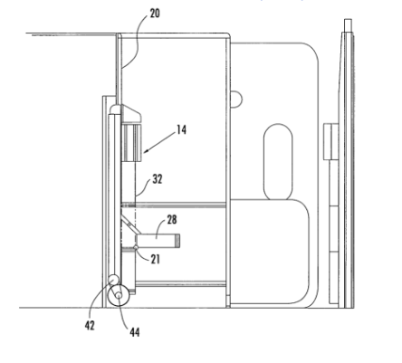
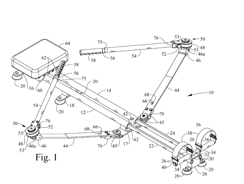
Figure 1: Device in stowed position

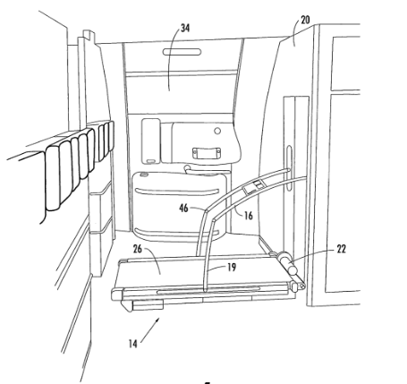
Figure 2: Device in deployed position

The treadmill will work like a typical treadmill you would find at your local gym. There will be a motor to drive the endless belt and its rollers. A possible motor would be a 2.5 horsepower DC motor that operates at 18 amps, 6700 rpm, and 130 VDC. This device is different from previous devices because it is meant for an airplane and doubles as a seat! There have previously been folding treadmills, but not one with a chair attached to it that can be used in the sky.

I think this a great idea that would benefit passengers who need a little bit of an extra stretch. Anyone on a long distance flight that wants to get his or her legs moving, and take a break from their seat would definitely use this device. This would especially benefit passengers who are at risk for DVT (deep vein thrombosis), because walking and stretching their legs would allow for increased blood flow.

Being someone who has been on a lot of international flights, I would definitely use this machine. After the first 5 hours of being on a flight my legs start to cramp, my back starts to hurt, and I get restless. If I were able to take a ten-minute walk mid flight, it would relieve the pain in my back and get the blood flowing in my legs again. It’s a great way to get passengers moving while 36,000 feet in the sky.

You can view the full patent here!

Skiing Imitating Apparatus

Spring Biased Ski Exercise Mounted On Adjustable Inclined Slope

Patent US3591172A filed on October 3, 1968
Issued: July 6, 1971
2.5 years to issue
Inventor: Franz Hude
US Classification: A63B69/18
10 Claims

This patent is a device used to imitate the movement performed when skiing. It consists of ski replicating members attached to a base that remains stationary. The rear ends of the skis pivot side to side to mimic the motions done while skiing. There are springs that attach the front of the skis to each other to provide resistance. There are also springs that connect the rear of the skis members to the rear of the base. A waistband is included in the device to give the user security and balance. The user can adjust the angles of the skis as well as the resistance applied. The device is meant to replicate the forces applied to a skier when executing different skiing drills. The user is required to adopt proper skiing positions and therefore the appropriate muscles, including the legs, hips, and ankles, are trained correctly when they use this device.

Figure 1: The user stands on the skis facing the narrow end of the base.

Someone who is interested in skiing both competitively and recreationally may be interested in using this technology. I think that if someone has never skied before and is nervous to get on a slope, this device might give them the confidence they need to get started. Older people who have never skied before and are self-conscious because they would be surrounded by other skiers who maybe started at a younger age may find this device helpful. It would also benefit professional skiers in the off season to prepare themselves and their muscles. Considering the device can be used anywhere on a flat surface, snow is not needed for someone to train in skiing. It may even be beneficial for coaches to be able to critique and give pointers to skiers while they are on the device after watching them practice.

The technology of this device includes springs, slider bars, and low friction material. The base also consists of several support pins and sockets to ensure the proper support of the apparatus, the correct amount of pivoting, and rotation. The springs that attach the front ends of the skis together provide the resistance necessary to allow the skis to rotate away from one another. The springs that connect the rear end of the skis to the back of the base provide the resistance a skier experiences when rotating about its longitudinal axis. The user can add more springs or remove them to change the resistance. The backs of the skis are attached to a bar that is elevated so the user is at a vertical angle. This incline can be adjusted by the user by sliding the slider bars forward or backwards, raising the back of the skis or lowering them. The underside of the ski members have a convex shape and are made of low friction material to easily pivot.

This device is novel in how is activates the same muscles involved in skiing as well as the movements involved. Previous devices have been designed to mimic the movement and perhaps give the user practice on balance, but they do not give the resistance that a skier would experience on the slopes. For example, Raymond E Armstrong designed a skiing simulator device that had skis on two treadmills which gave the user a chance to get a feel for the movements without fear of falling, but did not provide the challenge to the muscles that would be used.

I chose this patent because it wasn’t something I had seen before and thought it was a good idea. I personally have always wanted to ski or snowboard as it seems like a fun activity. However, I have also always been scared to fall or just be plain bad at it. I think that if I had access to this device I might feel more confident if I know the proper form I should have and my muscles were prepared for what they would feel in the actual snow. I also think that it would be a fun and different form of exercise as opposed to the boring elliptical or rowing machine.

How a Footwork Training System Can Improve Dance Training

Have you ever watched dancers on stage and think, how do they learn to do every moment at exactly the same time? The answer: lots and lots of practice. But, what if there was a way that would save them time and make sure they still perform in perfect unison? A system that a dance teacher could easily use in class? What if there was also a system that could help people track their own improvement at home?  Recently, there has been a huge need for home devices for personal training. However, at home training lacks in instructor feedback and also real-time evaluation and feedback. This led to the creation of the Footwork Training System and Method. I will explore this patent in how it works and the applications it is used for.

Patent Title: Footwork Training System and Method

Patent Number: US20080258921A1

Patent Filing Date: April 19, 2007

Patent Issue Date: October 23, 2008

How Long it Took to Issue: 1.5 years

Inventors: Helen Woo and Allan M.

Assignee: Nike, Inc.

U.S. Classification: A63B24/0006 – a computerized comparison for qualitative assessment of motion sequences or the course of movement

Claims: 50

            The system is comprised of several components: an article of clothing fit for the user’s body, a sensor attached to the article of clothing to detect the impact of the article of clothing against the surface, a processor connected to the sensor through a communication link, a target impact pattern accessible by the processor, and a display. The system is designed for a shoe. The processor and display are both a computer or portable electronic device. The purpose of this system is to provide an evaluation system for the user where while performing an activity, the sensor they are wearing can detect a performance impact pattern generated by the user. Then, the device can communicate the pattern to an evaluation system which will compare the performance impact pattern to the target impact pattern. The device can also store the information from the performance impact pattern.

Figure 1: The image on the left shows the shoe with sensors on it. The image on the right shows how when a person dances, the sensors in the shoe will collect the impact.

            The system works by determining a first performance metric based upon step, then the user can repeat the activity to generate a new performance pattern. Then, the system compares the new performance pattern to the target pattern to determine a new performance metric and finally, comparing the new performance pattern to the first performance metric to determine progress. The system will then display the performance pattern, new performance pattern, the target pattern, the first performance metric, and the new performance metric. The system can also be used for multiple users. This works by having a target impact pattern and then having each user wear the sensor. Then, the device compares the performance of the impact patter to the target impact pattern. Then the device will communicate the evaluation characteristics for the multiple users to a remote evaluation module via a communications network, which will compare the performances. The communication all occurs via the Internet and each user has access to a website that displays the results.

Figure 2: This chart depicts a simplified version of how the system works.

            In the references cited, there are various different patents that the device drew from including: music systems, shoe activated sound synthesized device, human movement measurement system, interactive surface and display system, sports electronic training system, and many others. The main difference with this device is that it incorporates different things from these patents to create a brand new device. It measures human movement patterns based on impact, which is different than some devices that record measurements visually. It also incorporates an interactive system and display which some devices have and others do not. It also is based on other shoe-like devices that have sensors or pads in them.

What I like about this device is that it can be used anywhere: it can be used at home, in class, in a gym, and a variety of other places. The creators list that this device is primarily used for dance, yoga posture, boxing moves, and martial arts movement. I primarily chose this patent because I thought how it was interesting how it is an evaluation tool for performance but can be used anywhere. I also liked how specifically the creators looked at how this device is used for dance. As a former dancer, I can clearly see the advantages of having a device like this. Not only can it be used to measure individual performance, it can also be used for multiple dancers which is definitely an advantage – it can help show if they are all performing in unison. When performing, all dancers want to be doing the same moves at the same time, and this device will help to evaluate that. I think that this device has so many applications and it can be further incorporated into not only a shoe, but a torso covering, leg covering, band, and jewelry. The possibilities seem endless for Footwork Training System and Method and it is really interesting to see where this goes in the future.


An Ocean Without Sharks

Patent title: Protective Swimsuit Incorporating an Electrical Wiring System

Patent number: US 20030233694 A1

Patent filing date: June 25, 2002

Patent issue date: December 25, 2003

How long it took for this patent to issue: 1.5 years

Inventor(s): Wescombe-Down, Michael

Assignee (if applicable): Wescombe-Down, Michael

U.S. classification: 2/2.15, 405/185, 405/186

How many claims: 10


Have you ever wanted to learn how to surf? What is the biggest thing that stops you from going out and getting a lesson? For most people, it is the fear of what animals might be lurking in the water below. Surfing can be one of the most beneficial exercises and unlike most workouts, its actually incredibly fun. Constantly paddling and swimming provides a great cardio workout, as well as strengthens your back and shoulder muscles. Standing up and balancing on the board then strengthens leg and core muscles as you get to enjoy riding the wave. This constant fear of sharks and other animals prevents so many people from gaining the benefits from this extraordinary exercise. However, this fear no longer needs to exist. Michael Wescombe-Down has patented a unique swimsuit that incorporates two electrodes connected to an electromagnetic field generator that allows for an electromagnetic field to be created around the user. This field in turn will prevent any aquatic creatures from entering close proximity to the wearer.

The suit’s power is supplied by a releasable electromagnetic field generator that is located near the waist region and has a status indicator visible to the user. This generator is connected to the two electrodes via two electrically conductive wires that run through the material of the suit. The wires are also releasable from the generator so that in case of emergency, the generator can be fully removed. Due to the conductivity of the sea water and the ions within, an electromagnetic current is able to be established between the electrodes. This current is then able to spread outward into a field through the conductive salt water. This electromagnetic field then works to repel sharks because of a special organ that sharks possess, Ampullae of Lorenzini. These are electroreceptors that are found in sharks and rays and so their sensors will be overstimulated and will deter them away from the source.


Figure 1: Depiction of the design of the suit (10) with the location of the generator (18) connected to the electrodes at each ankle (12, 14) by conductive wires (16).

Prior to this electromagnetic repellent technology there were two major strategies for avoiding sharks. One incorporated using stickers that slowly released a repellent substance as the water moved against the surface of it. The trouble with these was that the repellent was limited and a new sticker is required for every new trip into the water. The other strategy was using swim suits made of metal chain. These were more often only used for diving though rather than surfing so that the weight of the metal could be countered with the diving equipment. However, this technology is not really a repellent and more of just a protection against teeth if the sharks do bite. This was the first technology that was able to incorporate an electromagnetic repellent system into an average wetsuit that could be used for surfing as well as diving.

This swimsuit is perfect for people who have always been interested in surfing but have never tried because of their fears. It is also great for professional surfers who travel the world for great surfing locations that can be notorious for their shark populations. Even those who surf regularly for leisure would benefit from this device as it would just provide an extra piece of mind for anyone sitting out on their board with their legs dangling below the surface.

Personally, as a surfer, this suit has gripped me full attention. I have always been interested in shark repellent technologies and now there is one that is so attainable. When I surf with friends and I am able to converse the thought of animals below me completely escapes my mind. However, when I go alone or if I drift out farther than anyone and then realize I immediately get terrified and lift my limbs out of the water while paddling as fast as I can back to shore. Sitting on a board in the waves can be one of the most relaxing and peaceful experiences, but once the thought of sharks enters my mind it’s ruined. A wetsuit like this would be amazing for me as it would just allow me to sit out in the water alone, relax, and not have any fears tumbling through my mind.


To learn more about this patent click here.

Portable Rowing Machine

Patent Number: 9,005,086

Filing Date: August 28,2013

Issue Date: April 14, 2015

Inventors(s): O’Neil; John J. (Palm Harbor, FL)

Assignee: Hermann; Douglas L. (Clearwater, FL)

U.S. classification: 482/72

Claims: 16

  Fig. 1 Expanded view of the rowing machine for functional use

   Fig. 2, Collapsed view of the rowing machine

This exercise machine is a portable rowing machine which embodies a light weight frame and a more realistic rowing movement. The claims of this invention describe the overall structure and function of the machine. It claims to have a structural frame of two parallel tubular members connected to each other by three cross members and supported by floor brackets with tubular members inserted into the structural frame to allow for telescoping. A foot rest assembly locks partially to the third cross member and the frame to allow for stability of the user when in use.  Two swivel arms are pivotally attached to the first cross member which are able to be positioned parallel to the tubular member or perpendicular to the tubular member. Attached to the swivel arms are resistances that allow for comparable resistance experienced in rowing a boat. These resistances also include band brakes attached by clutch bearings for varying the frictional force. The oar arms of the rowing machine are attached to the resistance shafts and are extendable according to the user’s preference. The seat of the machine has rollers attached to the underside and is situated over the two structural tubular members. This allows for translation of the seat along the machine.

Competitive crew members, kayakers, and any rowing enthusiasts alike would be interested in using this portable rowing machine. The rowing machine changes the point of resistance from in front of the user to the side which is similar to the points of resistance experienced in a rowing boat. This can benefit competitive crew members who would like to train when they cannot train in the water, since this machine will train the same muscle groups with the same movements as those used in competition. According to the claims, the resistance between the swivel arms and oar allows for variance due to the clutch bearings so the resistance can be increased or decreased based on the preference of the user. This aspect can also be used for physical therapy to rehabilitate injured rowers. The portable rowing machine will allow for the rowing motion and an increase in resistance as the injury heals which will then increases arm-leg force production and core stabilization.

The portable rowing machine is based off of older oar-based rowing machines. The issue with these machines is that they were bulky, permanent structures that allowed for only one force of resistance. They mostly took half of a boat and attached it to a permanent structure, while this does allow for a realistic rowing motion it is not practical for most users. The current portable rowing machine combines the positive aspects of prior literature like of the off-set points of resistance with aspects that allow the machine to be portable, light weight, and suitable for a wider range of users. The novelty of the portable rowing machine is that it allows for variable resistance at off-set oar points to allow for various training conditions that maybe encountered while actually on the water.

I find this patent is interesting in that it is different from the typical rowing machines that you would find at the gym. The typical rowing machines have a bar attached to a tension cable that the user pulls on while also extending their legs. This means that the user might extend their arms and legs more than what is needed for the motion of rowing a boat. While this movement can be beneficial for the general exerciser in increasing arm-leg force production and increasing core stabilization; the movement can hinder competitive rowers who might want a more specific rowing movement. The patent moves the point of resistance from in front of the rower to perpendicular of the rower, where resistance typically occurs from the interaction of the oars with water. This provides a more natural rowing movement that a competitive rower would encounter during competitions. Another interesting aspect is that the machine is collapsible, which can reduce space taken up in a home gym or allow for easier mobility.

Learn more about this patent here.

Is There a Way to Improve My Shooting Form?

Shooting and training aid for basketball players

Patent Number: US 7442133 B2

Filed on May 19, 2006

Issued on October 28, 2008

Inventor: Jay W. Wolf

Assignee: Star Shooter Company, LLC

U.S. Classification: 473/450; 482/124

14 claims

One of the issues basketball players often face is not having a consistent shooting form. This problem partly occurs due to “off-hand interference”. “Off-hand interference” occurs when forces from the non-shooting hand interrupt the shooting hand when a shot is being generated. Instead of the shooting hand being used to generate a shot, both hands are used which causes an altered shot trajectory. Is there a way to fix this issue? The shooting and training aid for basketball players may provide a possible solution.

This shooting aid consists of three main components. The first component is a band that is strapped onto the non-shooting arm just above the elbow. The second component is a strap with two ends. One end of the strap is attached to the band just above the elbow while the other end of the strap consists of a loop. The loop will be placed on the base of the thumb of the non-shooting hand. The third, and final, component is a second strap. This strap also has two ends. One end of the strap is attached to the first strap at the base of the loop while the other end consists of a pocket. This pocket will be placed onto the middle finger of the non-shooting hand. As the basketball player shoots, the three components will tighten causing the thumb, middle finger, and other three fingers to release from the ball. By releasing the non-shooting hand from the ball, a more precise shot will be created. For a visual representation of the shooting aid, refer to Figure 1 below.

Figure 1: The shooting aid prior to starting the shooting formation (left) and directly after releasing the ball (right).

After the shooting aid has properly been placed onto the non-shooting arm, the basketball player will catch the ball then begin his/her shooting form. Once the arms raise the ball above the head, the three components of the shooting aid will stretch causing the non-shooting arm and hand to tighten. As the arm and hand tighten, the shooting aid will straighten and pull back the thumb and middle finger away from the ball. This will cause the other three fingers to also straighten and be pulled back. The non-shooting hand will then separate from the ball and the basketball player will be able to finish his/her shooting formation.

The engineering behind this device is in the forces that are prevented from being generated. The inventor claims that without using the shooting aid, the non-shooting hand has the ability to generate two forces that can alter a shot. The two forces are from a push in the vertical plane by the thumb and a rotation of the wrist inward in the horizontal plane causing the fingers to drag along the ball. By tightening the non-shooting arm and hand, the device is able to abduct the non-shooting arm away from the basketball as the player shoots so that the shooting arm is only used when generating a shot.

This device would work best for basketball players at any level who want to improve their shooting form as well as their shooting percentages. For example, children who are new to the game can use this device to learn how to shoot a basketball. From past experience, I know how difficult it is to correct your shooting form after initially learning how to shoot in a different way. This device would be beneficial for novices to the game so that they can learn how to shoot properly as early as possible.

This device is novel in the sense that it is one of the few shooting aids that focus on the non-shooting arm. Previous patents have focused mainly on the shooting arm with the goal of teaching basketball players how to follow through with their shot, not on the negative influences of the non-shooting arm. This device is also unique because it is the first shooting aid that prevents the fingers from dragging on the basketball as one shoots. The inventor of this device proposed two other patents in the past that focused on preventing forces by the thumb, but this device combines the previous concept with the concept of preventing the fingers from negatively influencing a shot.

I chose this patent mainly because I play basketball recreationally and have had difficulties in keeping a constant shooting form. It is interesting to see how a slight touch to the basketball from the non-shooting hand can have such adverse effects on a shot. Hopefully this device will help basketball players improve their performance and maybe I could try this device out to see if I can develop a more efficient shooting form.

To read more about this patent click here

A Lap Pool on a String?

Swimming exercise method and tether therefor
Patent Number: US 5846167 A
Filed Dec 29, 1997 – Issued Dec 8, 1998
Inventors: You Ching Liu, Samuel O. Engels
U.S. Classification: 482/55; 482/111
6 claims

Figures 1-4 are diagrams of the front and back of the harness, the tether and how the two look when in use.

Are you a swimmer that doesn’t have access to a big lap pool? Do you struggle with keeping your hips up at the surface for the most efficient stroke method? If you answered yes to one or both questions, then the swimming tether is the patent for you. The swimming tether allows you to swim in a confined space, while promoting efficient stroking technique.

The tether can be broken down into three key components: harness, line, and anchor. The latter two components are simple, an elongated, Y-shaped line with a hook or clip at all three ends for two attachment points on the swimmer and one to a fixed supporting object. These two components alone allow for someone to swim in place without moving, due to the constant horizontal reaction force that the line provides. Basically, you are playing tug-of-war with the wall. However, the claim that these two components provide, anchoring the swimmer helps you swim in place, is no different from any other swimming tether on the market. What gives this product the advantage is the claim that the harness provides; gives you the ability to swim in a more efficient technique. The harness attaches the swimmer to the line in a novel way. The harness fits around the torso like a normal vest in the front, and protrudes a little lower than the waist in the back. There are two anchor points on the shoulders to allow for the translation of your swimming force into the line. There is a loop located in the middle of the back just below the hip for the line to be freely threaded through. That loop functions to keep the hips up for stroke efficiency. There is no horizontal force at the hips because it is not a fixed anchor point. The tension in the line induces a normal force on the hips which keep them in line with the shoulders.

I choose this patent because it gives me flashback of training for varsity swimming in high school. Doing pulling drills on sprint days included tying a rope around our waists with the other end tied to the wall and we would have to sprint our hearts out for 30 seconds. It was terrible because the constant tension on our hips caused our legs to sink making us work much harder with our shoulders to keep us afloat and propel us forward. “You want to train like you race” our coach always said, so why were we training with our hips down trying to stop ourselves from drowning?

This patent takes the benefits of swimming in place and perfects them. By attaching to your shoulders and threatening the line through the loop at your hips, it automatically positions you for the most efficient stroke. This product can benefit a wide range of people from athletes to average Joes. People with space restrictions can use this for simulating swimming long distances without a lap pool. Athletes can use it for better training by being able to focus more on technique rather than drowning. By allowing the user to stay in shallow water, use proper form with ease, and its simplicity, this product is ideal for elderly, novices, and injured people for rehab or strength training.

The full patent can be viewed here

    The Treadmill of the Future?

    Have you ever been on a treadmill working out when suddenly you almost fall off the back of the machine? Have you ever found yourself struggling to keep up with a treadmill’s pace? Have you ever felt constrained by the preset speeds on a treadmill? You’re not the only one – many individuals have a tough time finding a pace that best suits them when running on a treadmill, to the point that pacing charts have been developed to make it easier for runners to find their ideal pace on the treadmill. But, what if this wasn’t a concern? What if treadmill speeds could be personalized to an individual? That’s the idea behind one US patent, the patent for a user footfall sensing control system for treadmill exercise machines:

    Patent title: User footfall sensing control system for treadmill exercise machines

    Patent number: US 8480541 B1

    Patent filing date: June 23, 2009

    Patent issue date: July 9, 2013

    How long it took for patent to issue: 4 years

    Inventors: Randall Thomas Brunts

    U.S. classification: 482/7

    Claims: 20

    This patent proposes to create a footfall monitoring system to track a treadmill user’s motion, speed, and acceleration to automatically adjust the speed of the treadmill to the user’s ideal pace. As the patent’s classification number denotes, the device is intended to “facilitate conditioning or developing of muscle” through “track, field, gymnastics, or athletic activity.” This device specifically will regulate the user’s “rate of movement” in order to facilitate positive exercise.

    This patent consists of 20 claims outlining the main functional components of the treadmill system. The main components of the device include: a tread base, a moving tread belt, a belt motion sensor to measure tread belt speed and displacement, a motor assembly to drive belt motion, a foot sensor to detect a user’s position on the tread belt, and a motor controller that adjusts the speed of the tread belt. The basic design for the system can be seen in Figure 1 below. These main components work together to register a user’s position and motion and then automatically change the speed of the tread belt in response to these measurements. While the details of how the system will measure and calculate differences in position, speed, and acceleration is somewhat complicated, the basic idea is simple – the treadmill will sense where a user is stepping on a treadmill and how long their strides are through capacitive proximity sensors around the tread base, as seen in Figure 1 on the right. By using measurements of timing between footfalls and positioning on the treadmill, the system will calculate the user’s speed, acceleration, and position on the treadmill relative to the “ideal” user position. These measurements can then be compared to the speed and acceleration of the tread belt, which can then be used to automatically fit the speed of the tread belt to the user’s running pace and get the runner back to the ideal position on the treadmill.

    This patent is not the first time a speed-changing treadmill has been patented before. Prior patents and art outline similar systems that measure a user’s position and speed on a treadmill. One main difference between this patent and other patents is the sensor type and sensing method used. Other proposed designs and patents used a variety of sensors, including optical sensors and pressure sensors as well as strain gauges, to detect a user’s position on a treadmill. However, these sensors often result in inaccurate or false-positive readings during use. This patent, on the other hand, uses capacitive proximity sensors. Using these sensors allows for higher precision and accuracy in footfall detection.


    Figure 1. External appearance of treadmill system (left), assembly and processing schematic for system (middle), and areas of footfall sensors (right).


    Why does this patent matter? Who is it going to help and how? The answer is – you! This patent has the potential to help everyone from elite athletes to the common gym-goer; anyone who uses a treadmill stands to benefit from this patent. I personally thought this patent was interesting and useful because of my own experiences with treadmills in the past. There have been times when I’m running on a treadmill and my pace changes without me really knowing or thinking about it; it’s a very slight, subtle pace change. But when this happens, I either end up running into the front of the treadmill or creeping backward on the treadmill to the point that I almost fall off the back edge of the machine. Because of this, I think it would be very useful, not to mention safer, to have a treadmill system that automatically adjusts to user pace changes.

    This patent and other exciting patents can be found through Google’s patent search or through a government patent search.

    Direct Measurement of Sweat Activity

    Method and Kit for Sweat Activity Measurement
    Patent Number: US 8,565,850 B2
    Filed July 1, 2008 – Issued December 22, 2009
    Inventors: Orjan Grottem Martinsen, Stabekk (NO); Sverre Joran Grimnes, Oslo (NO); Erik Fosse, Oslo (NO)
    U.S. Classification: USPC 600/346; 600/306
    15 claims

    The method and kit for sweat activity measurement is an invention that is aimed at directly measuring sweat activity. It does so by obtaining a measure for the degree of sweat duct filling, which is found to be a reliable estimate of sweat activity. Sweat ducts are the way through which sweat, produced in the sweat glands, is secreted onto the skin surface. The invention claimed is a kit for monitoring sweat activity, consisting of three electrodes to be placed on the subject’s skin and an electronic processing unit. This electronic processing unit applies a periodic signal to one of the electrodes, and a circuit measures the conductance signal received from another electrode. It can use identification of fluctuations in this signal to measure sweat activity. Additionally, it is able to determine a coefficient of change in sweat activity over time and activity level of the subject, using a signal analysis and frequency analysis module respectively. Additional claims include the ability to determine a quantitative expression for the sweat activity. Also, information obtained on the physiological state of the subject is claimed to relate to blood sugar.

    Based on the claims of this invention, this technology might be interested to several groups. It could be useful for physical training and exercise for several reasons. It can give an early warning of thermal imbalance of the body, it can be used to advice athletes on how much they should hydrate (especially given the variation of sweat rates), and it could potentially be useful for athletic trainers present at athlete’s practices and games to track the athlete’s hydration status. Medically this technology could be relevant for any scenario in which sweat levels are relevant, such as hidrosis (excessive sweat activity), illnesses and fever, such as malaria, diabetes and in general diagnostic activities correlating fever and sweating.

    The presented technology takes advantage of the conducting characteristics of the skin. The skin may be electrically modeled as a poorly conducting stratum corneum layer (the outer layer of the skin) shunted by sweat ducts containing variable amount of well conducting sweat. As sweat ducts fill, conductance increases. This is followed by a refractory period, during which sweat ducts empty themselves by a re-absorption process through the duct walls into surrounding epidermis layers. Hence, sweat activity is most strongly correlated with increase in conductance.

    The basic kit consists of several components, as shown in Figure 1. An electronic processing unit comprises operational amplifiers A and B, a signal multiplier X, a low pass filter LPF, and a conductance output G. V denotes a constant voltage generator. M, R, and C, respectively the measuring electrode, reference electrode, and current carrying electrode are placed on the skin, with an electrolyte providing electric contact between these electrodes (the lines from C to M indicate the electric current paths through the skin). Zsc and Zt denote the impedance of the stratum corneum and deeper layers of the skin respectively (note, impedance is a measurement of resistance to alternating currents, which is the same as resistance in direct currents).

    Figure 1. A schematic of the components of the method kit for sweat activity measurement. It shows circuit in the electronic processing unit, and the 3 electrodes (M, R, C) placed on the human skin.

    The circuit functions as follows. The voltage generator V, an oscillator, supplies a periodic signal with a predetermined frequency to the electrodes C via operational amplifier A. The current travels to electrodes M, after which the second operational amplifier B with a resistor R in the negative feedback loop serves as a current to voltage converter. Then, through multiplier X, the voltage is multiplied with the excitation sine wave signal from signal generator V by multiplier X. This allows to extract the real part, the conductance, from the complex admittance (a measure of the allowance of current). Remember, this conductance is the desired signal as it relates to sweat activity. Lastly, this multiplied signal is low pass filtered by LPF to obtain a direct current value proportional to the conductance in the skin. Remember, this is relevant since increased conductance is directly related to increased sweat activity. Some potential aspects of the design include incorporation of a micro controller to perform certain functions of the processing unit, reducing the number of separate components. Extension to a multi-channel system, for example by connecting a radio frequency transmitter, can potentially allow for data storage as well.

    In contrast to prior art, this technology provides a direct measurement of sweat activity. Here, a measure for the degree of sweat duct filling is obtained, which is directly related to sweat activity, as opposed to the indirect measurement of moisture content. Additionally, the inventors have taken into account that it is important that the measurement itself does not interfere too much with the filling of the sweat ducts, and they have discovered that prior art measurements did not take this into account. A previous intention also aimed at estimating sweat activity based on conductivity is inconvenient in use due to its complexity.

    I choose to discuss this particular patent based on the blog about electrolytes that I wrote earlier. Many studies that I read involved a way of measuring sweat, which is what got me thinking about the efficiency and accuracy of current methods. I think it is interesting that this invention allows for a convenient way to directly measure sweat activity. In addition to its relevance to exercise, sweat is also an indicator of for example lying, so I believe the invention has great potential for several applications.

    Additional information on this patent can be found here.

    Heart rate monitor for swimmers

    Heart Rate Monitor
    Patent 12459494 Filed on July 2, 2009
    Issued on January 21, 2010
    Inventors: John Mix and Roar Viala
    US Classification: 600/508
    20 claims

    This invention is an electronic athletic training device which measures heart rate for the purpose of aiding swimmers while training.  The main components of the device include a light sensor that measures changes in light due to blood flow in the skin, a micro-processor that calculates heart rate based on changes in the light detected by the infrared sensor, and a component to convert the output to audio signals representative of heart rate. To use this device, a user would position the infrared sensor near the temple using a clip that is attached to the strap of the user’s goggles. Additionally, the user would wear an earpiece which receives the audio signals. This device also has the ability to be powered by an internal lithium-ion rechargeable battery, be operated with a power button, and store the history of the user’s heart rate during workouts.

    I think this invention could be useful for Olympic swimmers as well as ordinary people who are interested in heart-rate-training and enjoy swimming.  For those interested in using this device for heart-rate training under moderate-intensity exercise this could be a very useful device. I think this is interesting because if I were to design a swimming workout based on my target heart-rate I would want to use this device. For swimmers, monitoring and maintaining target heart-rate for aerobic activity can be challenging using a typical wrist watch heart rate monitor, because it requires them to look at their wrist while swimming. I can understand how frequently glancing at a wrist heart rate monitor to get your heart-rate can be an annoyance for a swimmer. Therefore, this invention is novel because it removes that task altogether by providing the user with an audio rather than visual representation of heart rate.

    The technology of this device consists of infrared sensors that sit against the skin, and a microprocessor that is coupled to the sensors which calculates the number of beats/minute and generates output signals to an earpiece. The engineering behind this device is based on the principle of measuring the change in light through the user’s skin due to blood flow. Once that information is obtained, it is possible to calculate the heart rate by measuring the background noise with a separate infrared sensor and then subtracting it from the light measured via the infrared sensor at the skin’s surface.  The micro-processor then generates a correction factor for calculating the heart rate based on background noise.  Audio signals are generated through a transducer attached to the ear or temple wherein the transducer communicates the heart rate to the user’s ear where sounds are transferred. Aside from the actual device, the user also has the option of processing workout data from the heart monitor to generate a graphical representation of his/her heart rate on a computer.

    Figure 1. device showing infrared sensor and earpiece components of heart rate monitor

    This patent search was conducted on Espacenet. The source of this patent can be found here.