
Method and Kit for Sweat Activity Measurement
Patent Number: US 8,565,850 B2
Filed July 1, 2008 – Issued December 22, 2009
Inventors: Orjan Grottem Martinsen, Stabekk (NO); Sverre Joran Grimnes, Oslo (NO); Erik Fosse, Oslo (NO)
U.S. Classification: USPC 600/346; 600/306
15 claims
The method and kit for sweat activity measurement is an invention that is aimed at directly measuring sweat activity. It does so by obtaining a measure for the degree of sweat duct filling, which is found to be a reliable estimate of sweat activity. Sweat ducts are the way through which sweat, produced in the sweat glands, is secreted onto the skin surface. The invention claimed is a kit for monitoring sweat activity, consisting of three electrodes to be placed on the subject’s skin and an electronic processing unit. This electronic processing unit applies a periodic signal to one of the electrodes, and a circuit measures the conductance signal received from another electrode. It can use identification of fluctuations in this signal to measure sweat activity. Additionally, it is able to determine a coefficient of change in sweat activity over time and activity level of the subject, using a signal analysis and frequency analysis module respectively. Additional claims include the ability to determine a quantitative expression for the sweat activity. Also, information obtained on the physiological state of the subject is claimed to relate to blood sugar.
Based on the claims of this invention, this technology might be interested to several groups. It could be useful for physical training and exercise for several reasons. It can give an early warning of thermal imbalance of the body, it can be used to advice athletes on how much they should hydrate (especially given the variation of sweat rates), and it could potentially be useful for athletic trainers present at athlete’s practices and games to track the athlete’s hydration status. Medically this technology could be relevant for any scenario in which sweat levels are relevant, such as hidrosis (excessive sweat activity), illnesses and fever, such as malaria, diabetes and in general diagnostic activities correlating fever and sweating.
The presented technology takes advantage of the conducting characteristics of the skin. The skin may be electrically modeled as a poorly conducting stratum corneum layer (the outer layer of the skin) shunted by sweat ducts containing variable amount of well conducting sweat. As sweat ducts fill, conductance increases. This is followed by a refractory period, during which sweat ducts empty themselves by a re-absorption process through the duct walls into surrounding epidermis layers. Hence, sweat activity is most strongly correlated with increase in conductance.
The basic kit consists of several components, as shown in Figure 1. An electronic processing unit comprises operational amplifiers A and B, a signal multiplier X, a low pass filter LPF, and a conductance output G. V denotes a constant voltage generator. M, R, and C, respectively the measuring electrode, reference electrode, and current carrying electrode are placed on the skin, with an electrolyte providing electric contact between these electrodes (the lines from C to M indicate the electric current paths through the skin). Zsc and Zt denote the impedance of the stratum corneum and deeper layers of the skin respectively (note, impedance is a measurement of resistance to alternating currents, which is the same as resistance in direct currents).
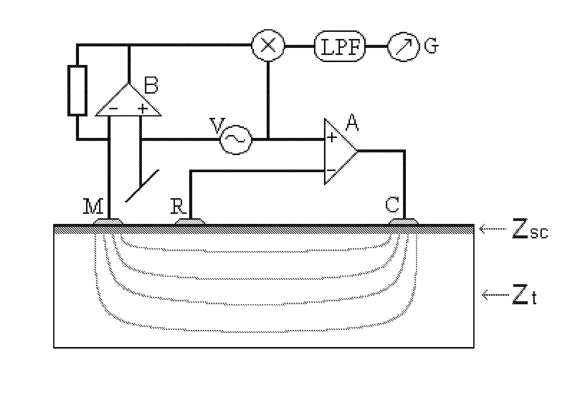
Figure 1. A schematic of the components of the method kit for sweat activity measurement. It shows circuit in the electronic processing unit, and the 3 electrodes (M, R, C) placed on the human skin.
The circuit functions as follows. The voltage generator V, an oscillator, supplies a periodic signal with a predetermined frequency to the electrodes C via operational amplifier A. The current travels to electrodes M, after which the second operational amplifier B with a resistor R in the negative feedback loop serves as a current to voltage converter. Then, through multiplier X, the voltage is multiplied with the excitation sine wave signal from signal generator V by multiplier X. This allows to extract the real part, the conductance, from the complex admittance (a measure of the allowance of current). Remember, this conductance is the desired signal as it relates to sweat activity. Lastly, this multiplied signal is low pass filtered by LPF to obtain a direct current value proportional to the conductance in the skin. Remember, this is relevant since increased conductance is directly related to increased sweat activity. Some potential aspects of the design include incorporation of a micro controller to perform certain functions of the processing unit, reducing the number of separate components. Extension to a multi-channel system, for example by connecting a radio frequency transmitter, can potentially allow for data storage as well.
In contrast to prior art, this technology provides a direct measurement of sweat activity. Here, a measure for the degree of sweat duct filling is obtained, which is directly related to sweat activity, as opposed to the indirect measurement of moisture content. Additionally, the inventors have taken into account that it is important that the measurement itself does not interfere too much with the filling of the sweat ducts, and they have discovered that prior art measurements did not take this into account. A previous intention also aimed at estimating sweat activity based on conductivity is inconvenient in use due to its complexity.
I choose to discuss this particular patent based on the blog about electrolytes that I wrote earlier. Many studies that I read involved a way of measuring sweat, which is what got me thinking about the efficiency and accuracy of current methods. I think it is interesting that this invention allows for a convenient way to directly measure sweat activity. In addition to its relevance to exercise, sweat is also an indicator of for example lying, so I believe the invention has great potential for several applications.
Additional information on this patent can be found here.
